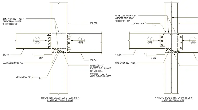
Steel beams frame into a steel column with vertically offset elevations requiring sloping continuity plates. The fifty KSI continuity plates are sized to the greater beam flange thickness plus one-eighth inch and welded with complete joint penetration welds on three sides typically. Where the offset exceeds the one-to-three slope, horizontal continuity plates are provided to align with both beam flanges.
TYPICAL VERTICAL OFFSET OF CONTINUITY PLATES AT COLUMN FLANGE TYPICAL VERTICAL OFFSET OF CONTINUITY PLATES AT COLUMN WEB STL BM STL BM 50 KSI CONTINUITY PL'S = GREATER BM FLANGE THICKNESS + 1/8" 50 KSI CONTINUITY PL'S = GREATER BM FLANGE THICKNESS + 1/8" STL BM STL COL WHERE OFFSET EXCEEDS THE 1:3 SLOPE, PROVIDE HORIZ CONTINUITY PLS TO ALIGN W/ BOTH FLANGES SLOPE CONTINUITY PL'S 1 3 MIN 1 S802 1 S802 1 S802 1 S802 1 3 MIN SLOPE CONTINUITY PL'S CJP SIDES TYP CJP (3) SIDES TYP TYPICAL VERTICAL OFFSET OF CONTINUITY PLATES AT COLUMN FLANGE TYPICAL VERTICAL OFFSET OF CONTINUITY PLATES AT COLUMN WEB STL BM STL BM 50 KSI CONTINUITY PL'S = GREATER BM FLANGE THICKNESS + 1/8" 50 KSI CONTINUITY PL'S = GREATER BM FLANGE THICKNESS + 1/8" STL BM STL COL WHERE OFFSET EXCEEDS THE 1:3 SLOPE, PROVIDE HORIZ CONTINUITY PLS TO ALIGN W/ BOTH FLANGES SLOPE CONTINUITY PL'S 1 3 MIN 1 S802 1 S802 1 S802 1 S802 1 3 MIN SLOPE CONTINUITY PL'S CJP SIDES TYP CJP (3) SIDES TYP
Members view this detail in full resolution, download the CAD files (SVG, PDF), and can adapt it in the built-in CAD editor — export DXF, DWG, or PDF.
Start membership