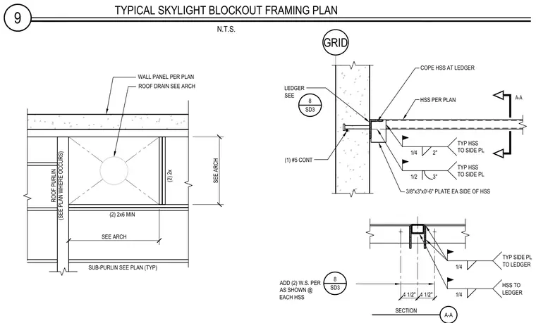
Hollow structural section framing members connect to a structural ledger at a wall with a three-eighths-inch by three-inch by zero-foot-six-inch plate on each side of the hollow structural section, welded with quarter-inch and half-inch fillet welds. Two two-by-six minimum wood members and two two-by sub-purlins frame the roof opening alongside a roof purlin and wall panels per plan. Section A-A shows the hollow structural section coped at the ledger with continuous reinforcing bars embedded in the wall and additional weld symbols as shown at each hollow structural section.
9 TYPICAL SKYLIGHT BLOCKOUT FRAMING PLAN N.T.S. 8 SD3 A-A 4 1/2" 4 1/2" A-A SECTION GRID (2) 2x6 MIN (2) 2x SUB-PURLIN SEE PLAN (TYP) WALL PANEL PER PLAN ROOF DRAIN SEE ARCH ROOF PURLIN (SEE PLAN WHERE OCCURS) SEE ARCH SEE ARCH COPE HSS AT LEDGER HSS PER PLAN LEDGER SEE (1) #5 CONT 1/4 2" TYP HSS TO SIDE PL 1/2 3" TYP HSS TO SIDE PL 3/8"x3"x0'-6" PLATE EA SIDE OF HSS ADD (2) W.S. PER AS SHOWN @ EACH HSS 8 SD3 1/4 TYP SIDE PL TO LEDGER 1/4 HSS TO LEDGER
Members view this detail in full resolution, download the CAD files (SVG, PDF), and can adapt it in the built-in CAD editor — export DXF, DWG, or PDF.
Start membership