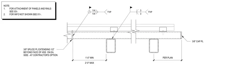
The assembly features a hollow structural section supporting framing member capped with a three-eighths-inch cap plate welded typically with quarter-inch fillets. A three-eighths-inch splice plate extends one-half inch beyond the face of the hollow structural section on each side, positioned at the contractor's option. Spacing is maintained between one foot minimum and two feet maximum per plan.
1/4 1/4 TYP 3/8" CAP PL 3/8" SPLICE PL EXTENDING 1/2" BEYOND FACE OF HSS ON EA. SIDE - AT CONTRACTOR'S OPTION PER PLAN 2'-0" MAX 1'-0" MIN 3 3 TYP 1. 2. NOTE: FOR ATTACHMENT OF PANELS AND RAILS SEE 03/-. FOR INFO NOT SHOWN SEE 01/-.
Members view this detail in full resolution, download the CAD files (SVG, PDF), and can adapt it in the built-in CAD editor — export DXF, DWG, or PDF.
Start membership