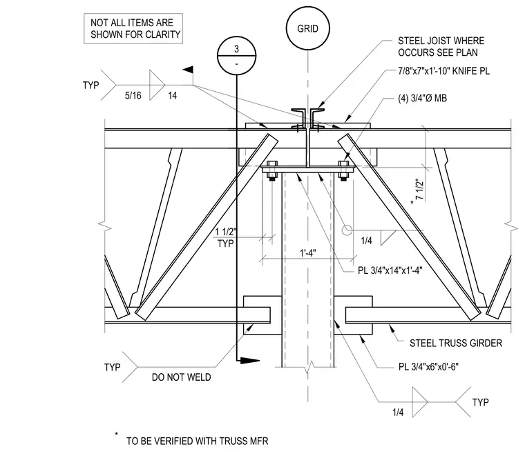
A steel truss girder bears onto a column supported by a 3/4-inch by 14-inch by 1-foot-4-inch cap plate secured with four 3/4-inch diameter machine bolts. A 7/8-inch by 7-inch by 1-foot-10-inch knife plate ties into the top chord with a steel joist located per plan. A 3/4-inch by 6-inch by 0-foot-6-inch plate is left unwelded to the girder per note, with dimensions verified by the truss manufacturer. Fillet welds of 1/4-inch and 5/16-inch sizes are applied throughout the assembly typical to the connection details.
TYP TYP TYP 1 1/2" TYP 7 1/2" 1'-4" GRID PL 3/4"x6"x0'-6" TO BE VERIFIED WITH TRUSS MFR DO NOT WELD PL 3/4"x14"x1'-4" 7/8"x7"x1'-10" KNIFE PL STEEL JOIST WHERE OCCURS SEE PLAN 3 - STEEL TRUSS GIRDER * * (4) 3/4"Ø MB NOT ALL ITEMS ARE SHOWN FOR CLARITY 1/4 1/4 5/16 14
Members view this detail in full resolution, download the CAD files (SVG, PDF), and can adapt it in the built-in CAD editor — export DXF, DWG, or PDF.
Start membership