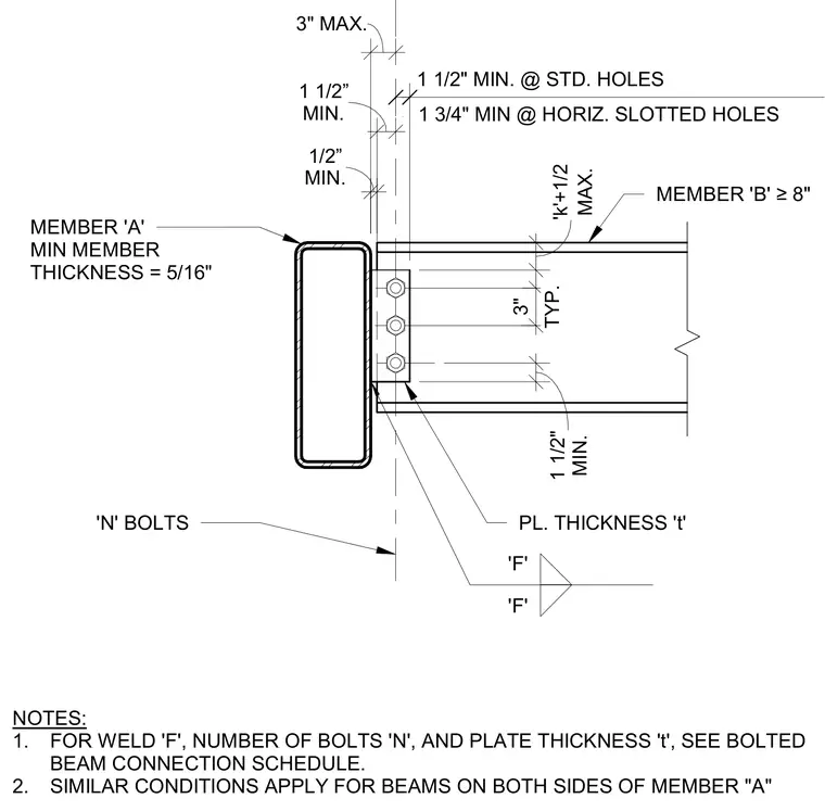
A wide flange beam labeled member B connects to a hollow structural section column labeled member A through a welded shear plate of thickness t. The supporting hollow structural section column has a minimum member thickness of five-sixteenths of an inch. The supported beam requires a minimum depth of eight inches with standard holes maintaining one and one-half inch minimum edge distance and horizontal slotted holes maintaining one and three-quarter inch minimum edge distance. Three-inch typical bolt spacing applies vertically with one and one-half inch minimum spacing to the beam flanges. Weld size F, number of bolts N, and plate thickness t are determined from the bolted beam connection schedule. Similar conditions apply for beams framing into both sides of the column.
MEMBER 'B' ≥8" 1 3/4" MIN @ HORIZ. SLOTTED HOLES 1 1/2" MIN. @ STD. HOLES PL. THICKNESS 't' NOTES: 1. FOR WELD 'F', NUMBER OF BOLTS 'N', AND PLATE THICKNESS 't', SEE BOLTED BEAM CONNECTION SCHEDULE. 2. SIMILAR CONDITIONS APPLY FOR BEAMS ON BOTH SIDES OF MEMBER "A" MEMBER 'A' MIN MEMBER THICKNESS = 5/16" 'N' BOLTS TYP. 3" MIN. 1 1/2" MIN. 1 1/8" 'F' 'F' MIN. 1/2” 3" MAX. MAX. 'k'+1/2 MIN. 1 1/2”
Members view this detail in full resolution, download the CAD files (SVG, PDF), and can adapt it in the built-in CAD editor — export DXF, DWG, or PDF.
Start membership