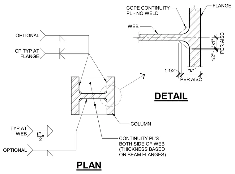
Continuity plates are placed on both sides of the column web with a thickness based on the connecting beam flanges. The plates feature a coped corner left unwelded near the column fillet, conforming to AISC dimension requirements. Fillet welds connect the continuity plate to the column web and flanges as indicated in the plan layout.
DETAIL PLAN COLUMN WEB FLANGE COPE CONTINUITY PL - NO WELD 1/2" PER AISC "k1" 1 1/2" PER AISC "k" CONTINUITY PL'S BOTH SIDE OF WEB (THICKNESS BASED ON BEAM FLANGES) TYP AT WEB tPL 2 OPTIONAL CP TYP AT FLANGE OPTIONAL
Members view this detail in full resolution, download the CAD files (SVG, PDF), and can adapt it in the built-in CAD editor — export DXF, DWG, or PDF.
Start membership