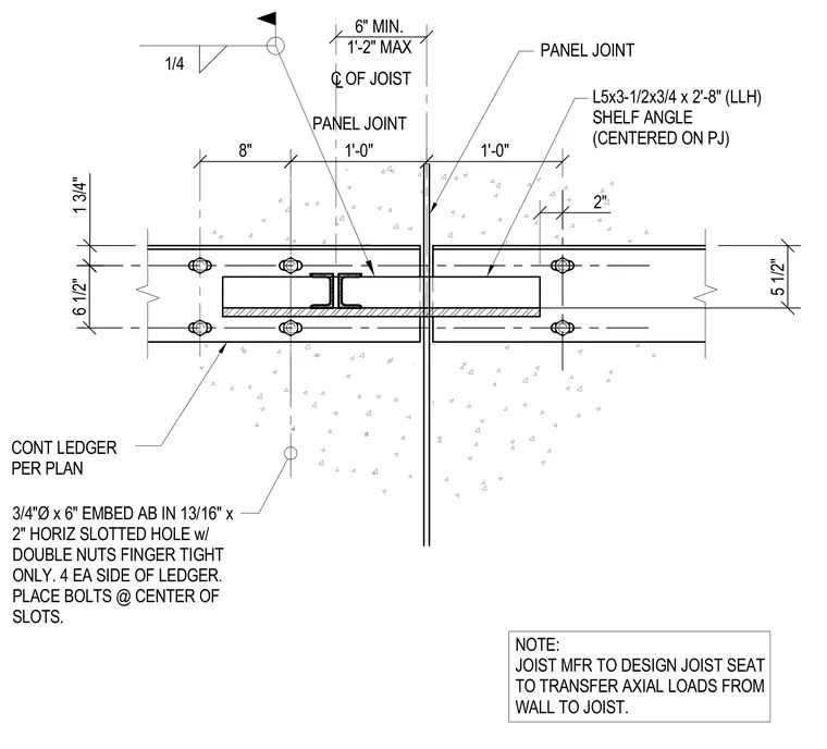
A continuous ledger angle (per plan) and a 5 inch by 3-1/2 inch by 3/4 inch by 2 feet 8 inches long-leg horizontal shelf angle are centered across a vertical panel joint. The shelf angle connects to the wall using three-quarter-inch diameter by 6-inch embedded anchor bolts placed in 13/16-inch by 2-inch horizontal slotted holes with double nuts finger-tight only, with four anchor bolts on each side of the ledger. Bolts are positioned at the center of the slots to allow movement, maintaining a 6-inch minimum to 1-foot 2-inch maximum spacing from the centerline of the joist. A 1/4-inch weld is indicated at the upper connection. The joist manufacturer must design the joist seat to transfer axial loads from the wall to the joist.
1'-0" 5 1/2" 8" 6 1/2" 1 3/4" 6" MIN. 1'-2" MAX 1'-0" 2" NOTE: JOIST MFR TO DESIGN JOIST SEAT TO TRANSFER AXIAL LOADS FROM WALL TO JOIST. CONT LEDGER PER PLAN PANEL JOINT 1/4 3/4"Ø x 6" EMBED AB IN 13/16" x 2" HORIZ SLOTTED HOLE w/ DOUBLE NUTS FINGER TIGHT ONLY. 4 EA SIDE OF LEDGER. PLACE BOLTS @ CENTER OF SLOTS. PANEL JOINT C OF JOIST L L5x3-1/2x3/4 x 2'-8" (LLH) SHELF ANGLE (CENTERED ON PJ)
Members view this detail in full resolution, download the CAD files (SVG, PDF), and can adapt it in the built-in CAD editor — export DXF, DWG, or PDF.
Start membership