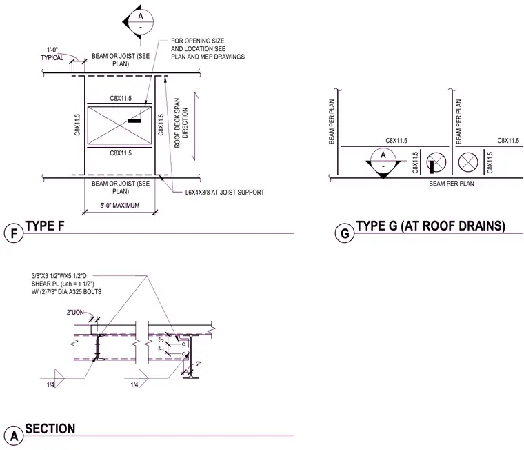
Framing details for roof openings and roof drains utilize C8x11.5 channel members and angle supports. Opening dimensions, spacing, and MEP coordination are governed per structural and mechanical plans with a maximum spacing of 5'-0". Framing connections incorporate a 3/8" x 3 1/2" x 5 1/2" shear plate fastened with two 7/8" diameter A325 bolts and 1/4" fillet welds. Additional support includes an L6x4x3/8 angle at joist supports typical.
A - A - C8X11.5 C8X11.5 C8X11.5 ROOF DECK SPAN DIRECTION FOR OPENING SIZE AND LOCATION SEE PLAN AND MEP DRAWINGS 5'-0" MAXIMUM C8X11.5 BEAM OR JOIST (SEE PLAN) 3/8"X3 1/2"WX5 1/2"D SHEAR PL (Leh = 1 1/2") W/ (2)7/8" DIA A325 BOLTS 1/4 1/4 3" 3" 2" 2"UON BEAM OR JOIST (SEE PLAN) L6X4X3/8 AT JOIST SUPPORT TYPICAL 1'-0" A SECTION F TYPE F BEAM PER PLAN C8X11.5 BEAM PER PLAN BEAM PER PLAN G TYPE G (AT ROOF DRAINS) C8X11.5 C8X11.5 C8X11.5 A - A - C8X11.5 C8X11.5 C8X11.5 ROOF DECK SPAN DIRECTION FOR OPENING SIZE AND LOCATION SEE PLAN AND MEP DRAWINGS 5'-0" MAXIMUM C8X11.5 BEAM OR JOIST (SEE PLAN) 3/8"X3 1/2"WX5 1/2"D SHEAR PL (Leh = 1 1/2") W/ (2)7/8" DIA A325 BOLTS 1/4 1/4 3" 3" 2" 2"UON BEAM OR JOIST (SEE PLAN) L6X4X3/8 AT JOIST SUPPORT TYPICAL 1'-0" A SECTION F TYPE F BEAM PER PLAN C8X11.5 BEAM PER PLAN BEAM PER PLAN G TYPE G (AT ROOF DRAINS) C8X11.5 C8X11.5 C8X11.5
Members view this detail in full resolution, download the CAD files (SVG, PDF), and can adapt it in the built-in CAD editor — export DXF, DWG, or PDF.
Start membership