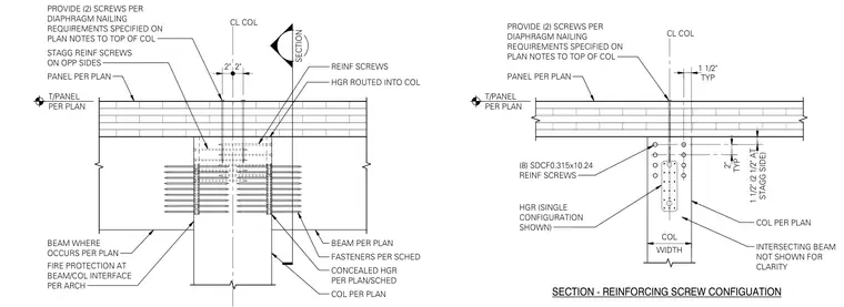
Reinforcing screw configuration at a beam-to-column intersection supporting a panel per plan. Staggered reinforcing screws are installed on opposite sides of the column centerline with specified edge distances and spacing. A concealed hanger is routed into the column and secured with fasteners per schedule. Fire protection is provided at the beam-to-column interface as specified by architectural drawings. Diaphragm nailing requirements apply two screws to the top of the column.
SECTION BEAM PER PLAN PANEL PER PLAN REINF SCREWS BEAM WHERE OCCURS PER PLAN CL COL T/PANEL PER PLAN STAGG REINF SCREWS ON OPP SIDES HGR ROUTED INTO COL FASTENERS PER SCHED CONCEALED HGR PER PLAN/SCHED FIRE PROTECTION AT BEAM/COL INTERFACE PER ARCH COL PER PLAN SECTION - REINFORCING SCREW CONFIGUATION CL COL T/PANEL PER PLAN TYP 1 1/2" TYP 2" STAGG SIDE) 1 1/2" (2 1/2" AT WIDTH COL (8) SDCF0.315x10.24 REINF SCREWS HGR (SINGLE CONFIGURATION SHOWN) COL PER PLAN PANEL PER PLAN INTERSECTING BEAM NOT SHOWN FOR CLARITY 2" 2" PROVIDE (2) SCREWS PER DIAPHRAGM NAILING REQUIREMENTS SPECIFIED ON PLAN NOTES TO TOP OF COL PROVIDE (2) SCREWS PER DIAPHRAGM NAILING REQUIREMENTS SPECIFIED ON PLAN NOTES TO TOP OF COL
Members view this detail in full resolution, download the CAD files (SVG, PDF), and can adapt it in the built-in CAD editor — export DXF, DWG, or PDF.
Start membership