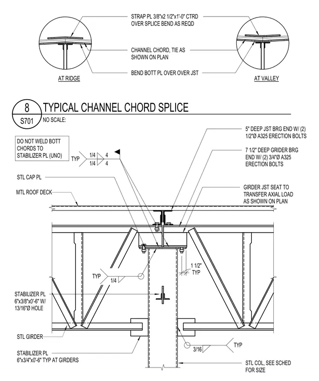
A channel chord splice assembly occurs at a steel column and steel girder supporting metal roof deck. A steel cap plate is welded to the top of the steel column with a typical fillet weld, with bottom chords left unwelded to the stabilizer plate unless noted otherwise. A three-eighths by two-and-a-half by twelve-inch strap plate is centered over the splice and bent as required, featuring variations for ridge and valley conditions. A six-by-three-eighths-inch stabilizer plate with a thirteen-sixteenths-inch diameter hole connects to the assembly, alongside a six-by-three-quarters-inch stabilizer plate provided at the girders. The seven-and-a-half-inch deep steel girder bearing end connects using two three-quarters-inch diameter ASTM A325 erection bolts, while the five-inch deep joist bearing end connects with two one-half-inch diameter ASTM A325 erection bolts. The girder joist seat transfers axial load as shown on plan.
STRAP PL 3/8"x2 1/2"x1'-0" CTRD OVER SPLICE BEND AS REQD CHANNEL CHORD, TIE AS SHOWN ON PLAN BEND BOTT PL OVER OVER JST AT RIDGE AT VALLEY STL CAP PL DO NOT WELD BOTT CHORDS TO STABILIZER PL (UNO) TYP 3/16 MTL ROOF DECK STL GIRDER STABILIZER PL 6"x3/4"x0'-6" TYP AT GIRDERS STL COL, SEE SCHED FOR SIZE TYP 1 1/2" STABILIZER PL 6"x3/8"x0'-6" W/ 13/16"Ø HOLE TYP 1/4 7 1/2" DEEP GRIDER BRG END W/ (2) 3/4"Ø A325 ERECTION BOLTS 5" DEEP JST BRG END W/ (2) 1/2"Ø A325 ERECTION BOLTS 1/4 TYP 1/4 4 4 GIRDER JST SEAT TO TRANSFER AXIAL LOAD AS SHOWN ON PLAN NO SCALE: S701 8 TYPICAL CHANNEL CHORD SPLICE
Members view this detail in full resolution, download the CAD files (SVG, PDF), and can adapt it in the built-in CAD editor — export DXF, DWG, or PDF.
Start membership