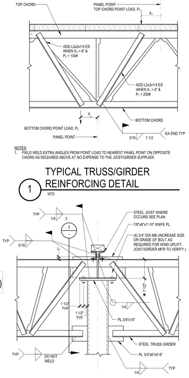
A structural steel truss girder is reinforced for concentrated top and bottom chord point loads with additional angles on each side. A steel joist bears onto the top chord via a seven-eighths-inch by six-inch by one-foot-ten-inch knife plate secured with four three-quarter-inch diameter machine bolts, with bolt size or grade subject to increase for wind uplift as verified by the joist or girder manufacturer. The truss girder connects to the supporting steel column using a three-quarter-inch by fourteen-inch plate and a three-quarter-inch by six-inch by zero-foot-six-inch plate with specific fillet welds, leaving certain areas unwelded to the girder as noted. Field weld extra angles from the point load to the nearest panel point on the opposite chord as required when dimensions and point loads exceed specified thresholds.
PANEL POINT TOP CHORD POINT LOAD, P 1 TOP CHORD ADD L2x2x1/4 ES WHEN X 2 > 6" & P 2 > 100# X 1 ADD L2x2x1/4 ES WHEN X 1 > 6" & P 1 > 250# BOTTOM CHORD 3/16 1 1/2 EA END TYP 2 BOTTOM CHORD POINT LOAD, P 2 PANEL POINT NOTES: 1. FIELD WELD EXTRA ANGLES FROM POINT LOAD TO NEAREST PANEL POINT ON OPPOSITE CHORD AS REQUIRED ABOVE AT NO EXPENSE TO THE JOIST/GIRDER SUPPLIER. X STEEL JOIST WHERE OCCURS SEE PLAN 7/8"x6"x1'-10" KNIFE PL (4) 3/4" DIA MB (INCREASE SIZE OR GRADE OF BOLT AS REQUIRED FOR WIND UPLIFT. JOIST/GIRDER MFR TO VERIFY.) 1/4 3 TYP 5/16 TYP 1/4 PL 3/4"x14" STEEL TRUSS GIRDER PL 3/4"x6"x0'-6" 1/4 TYP DO NOT WELD TYP TYP 1 1/2" TYP 1 1/2" 7 1/2" * 1" 3 - NTS TYPICAL TRUSS/GIRDER REINFORCING DETAIL 1
Members view this detail in full resolution, download the CAD files (SVG, PDF), and can adapt it in the built-in CAD editor — export DXF, DWG, or PDF.
Start membership