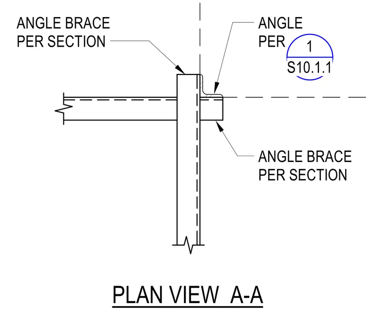
This plan view details a structural angle brace connection configured per section. The layout includes an angle brace specified as per section alongside an angle per detail 1 on sheet S10.1.1. Centerlines establish alignment for the intersecting members.
ANGLE BRACE PER SECTION ANGLE BRACE PER SECTION PLAN VIEW A-A ANGLE PER 1 S10.1.1
Members view this detail in full resolution, download the CAD files (SVG, PDF), and can adapt it in the built-in CAD editor — export DXF, DWG, or PDF.
Start membership