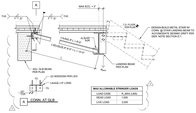
A design-build metal stair connection at a stair landing beam is configured to accommodate seismic drift per general notes. The assembly frames between an adjacent glulam beam and a structural landing beam located per plan, featuring a three-inch maximum eccentricity. Angle sizes vary based on span length, using three-by-three by one-quarter inch angles for spans under eight feet and three-and-one-half by three-and-one-half by three-eighths inch angles for spans between eight and twelve feet. Two SDS25350 fasteners connect each leg through a four-by-four by one-quarter inch angle eight inches long. A three-eighths by four-and-one-half inch square plate is welded with quarter-inch fillet welds typically.
DESIGN-BUILD METAL STAIR W/ CONN. @ STAIR LANDING BEAM TO ACCOMODATE SEISMIC DRIFT PER GEN. NOTE SECTION D.1 LANDING BEAM PER PLAN R MAX MAX ECC. = 3" T.O. FLOOR PER PLAN TYP. 3 14 " PL 3 8 x4 1 2 " SQR. TYP. 2 14 " L L3x3x 1 4 IF L < 8'-0" L3 1 2 x3 12 x 3 8 IF 8'-0" < L < 12'-0" ADJ. GLB BEAM, PER PLAN MAX ALLOWABLE STRINGER LOADS LOAD CASE R_MAX (LBS) DEAD LOAD 1,000 LIVE LOAD 2,000 1 L4x4x 1 4 x 8" LONG (2) SDS25350 PER LEG 1 1 2 " TYP. A CONN. AT GLB CL CL A 1
Members view this detail in full resolution, download the CAD files (SVG, PDF), and can adapt it in the built-in CAD editor — export DXF, DWG, or PDF.
Start membership