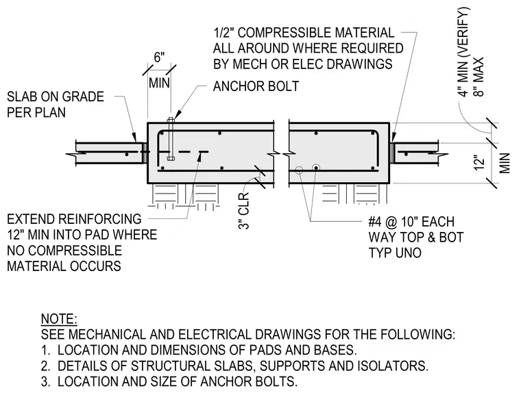
A concrete equipment pad is cast adjacent to a slab on grade with a half-inch compressible material separating the two where required by mechanical or electrical drawings. Reinforcing consists of number four bars at ten inches each way top and bottom typically unless noted otherwise, extending twelve inches minimum into the pad where no compressible material occurs. The pad requires a three-inch clear cover and features embedded anchor bolts for equipment attachment. A four-inch minimum to eight-inch maximum depth transitions into a twelve-inch thick pad section.
NOTE: SEE MECHANICAL AND ELECTRICAL DRAWINGS FOR THE FOLLOWING: 1. LOCATION AND DIMENSIONS OF PADS AND BASES. 2. DETAILS OF STRUCTURAL SLABS, SUPPORTS AND ISOLATORS. 3. LOCATION AND SIZE OF ANCHOR BOLTS. ANCHOR BOLT #4 @ 10" EACH WAY TOP & BOT TYP UNO 1/2" COMPRESSIBLE MATERIAL ALL AROUND WHERE REQUIRED BY MECH OR ELEC DRAWINGS EXTEND REINFORCING 12" MIN INTO PAD WHERE NO COMPRESSIBLE MATERIAL OCCURS MIN 6" 3" CLR MIN 12" 4" MIN (VERIFY) 8" MAX SLAB ON GRADE PER PLAN
Members view this detail in full resolution, download the CAD files (SVG, PDF), and can adapt it in the built-in CAD editor — export DXF, DWG, or PDF.
Start membership