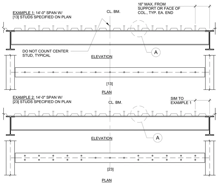
These elevation and plan diagrams illustrate shear stud layouts on composite steel beams spanning between columns. The layouts show stud placement relative to the centerline of the beam, requiring a maximum spacing of sixteen inches from the support or face of the column at each end. Example one displays thirteen studs specified on plan with a note to exclude the center stud from the count. Example two details twenty-three studs spaced similarly along the member.
EXAMPLE 1: 14'-0" SPAN W/ [13] STUDS SPECIFIED ON PLAN CL. BM. DO NOT COUNT CENTER STUD, TYPICAL EXAMPLE 2: 14'-0" SPAN W/ [23] STUDS SPECIFIED ON PLAN ELEVATION ELEVATION PLAN PLAN . 16" MAX. FROM SUPPORT OR FACE OF COL., TYP. EA. END [13] CL. BM. . SIM TO EXAMPLE 1 A [23] A
Members view this detail in full resolution, download the CAD files (SVG, PDF), and can adapt it in the built-in CAD editor — export DXF, DWG, or PDF.
Start membership