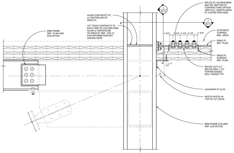
A structural drag plate connects to a steel buckling-restrained braced frame column and a cross-laminated timber deck. One-half-inch-thick continuity plates are positioned on each side of the column web, aligned with the centerline of the drag plate. The cross-laminated timber deck is notched by four inches at the column and routed out a maximum of one and one-half inches below for recessed bolt heads. A structural angle measuring L6x4x3/8 by zero feet eight inches supports the assembly, while drag plate screws secure the plate to the timber deck beneath a gypcrete topping. A splice plate is provided as required but may be omitted at the contractor's option in favor of a full-length drag plate.
1/2" THICK CONTINUITY PL EACH SIDE OF COLUMN WEB ALIGN w/ CENTERLINE OF DRAG PL REF. 3/S3.13 FOR INFORMATION NOT SHOWN HERE BRB FRAME REF. PLAN AND ELEVATION ALIGN CONTINUITY PL w/ CENTERLINE OF DRAG PL 2 S3.13 _____ BRB FRAME COLUMN REF. ELEVATION 4" NOTCH WIDTH IN TOP OF CLT DECK DRAG PL SCREWS REF. PLAN DRAG PL REF. PLAN GYPCRETE TOPPING REF. ARCH. 1 3/4" 3 1/2" 3 1/2" 3 1/2" 1 3/4" 3 S3.13 _____ ROUTE OUT CLT BELOW MAX 1 1/2" FOR RECESSED BOLT HEADS TYP. 1" L6x4x3/8x0'-8" (LLH) SPLICE PL AS REQUIRED MAY BE OMITTED AT CONTRACTORS OPTION AND FULL LENGTH DRAG PL CAN BE PROVIDED
Members view this detail in full resolution, download the CAD files (SVG, PDF), and can adapt it in the built-in CAD editor — export DXF, DWG, or PDF.
Start membership