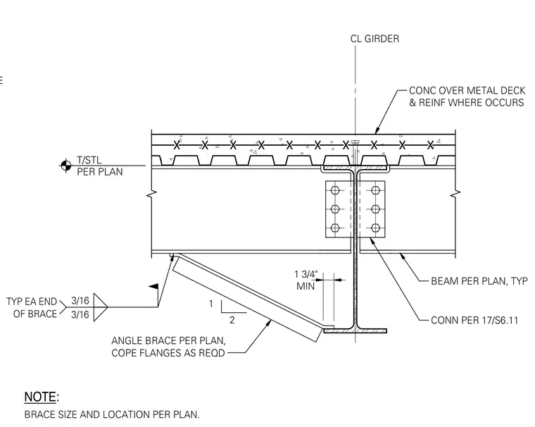
An angle brace connects to the bottom flange of a steel beam framing into a girder centerline, with beam flanges coped as required and a one-and-three-quarter-inch minimum clearance maintained. Three-sixteenth-inch fillet welds are specified at each end of the brace. The beam connects to the girder web using typical connection plates and bolts sized per plan. A concrete slab over metal deck with reinforcement sits above the steel framing.
CONC OVER METAL DECK & REINF WHERE OCCURS CL GIRDER BEAM PER PLAN, TYP CONN PER 17/S6.11 ANGLE BRACE PER PLAN, COPE FLANGES AS REQD 3/16 3/16 TYP EA END OF BRACE 1 2 MIN 1 3/4" NOTE: BRACE SIZE AND LOCATION PER PLAN. T/STL PER PLAN TYP T&B FLANGE
Members view this detail in full resolution, download the CAD files (SVG, PDF), and can adapt it in the built-in CAD editor — export DXF, DWG, or PDF.
Start membership