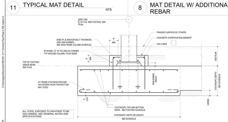
A structural steel column base plate is anchored to a reinforced concrete mat footing using anchor bolts sized per the non-frame column schedule, with non-shrink grout placed beneath the plate. The concrete footing includes top and bottom reinforcing mats sized per the schedule, with a minimum three-inch clear cover and one-hundred-eighty-degree hooks provided for bottom mat steel at frame footings. Number four dowels are placed at sixteen inches on center at each corner and typically around all four sides of the column. A concrete overpour encasement with two number four U-bars surrounds the base of the column above the footing top.
FOOTING/PC TOP AND BOTTOM REINF - SEE FOOTING SCHEDULE BASE PL & ANCHOR BOLT THICKNESS, SIZE AND NUMBER - SEE NON-FRAME COLUMN SCHEDULE GRID LINE, OF COL AND FOOTING, SEE PLAN #4 DOWEL AT 16" OC AND EA CORNER TYP AROUND COLUMN, FOUR SIDES AT FRAME FOOTINGS PROVIDE 180 DEGREE HOOK FOR BOTTOM MAT STEEL SEE SCHEDULE FOOTING/PC WIDTH OR LENGTH SEE SCHEDULE FOOTING/PC DEPTH . GROUT NON-SHRINK SEE PLAN TOP OF FOOTING/ GRADE BEAM SEE PLAN CLR 3" VARIES MIN 8" CONCRETE OVERPOUR ENCASEMENT 2-#4 U-BAR FINISHED SURFACE BY OTHERS MIN 6" ALL STEEL EXPOSED TO WEATHER TO BE GALVANIZED, SEE GENERAL NOTES AND SPECIFICATIONS C:\Users\eagnes\Documents\19001941- 2111 University Plaza Phase 2_R20_eagnes.rvt NTS 11 TYPICAL MAT DETAIL 8 MAT DETAIL W/ ADDITIONAL REBAR
Members view this detail in full resolution, download the CAD files (SVG, PDF), and can adapt it in the built-in CAD editor — export DXF, DWG, or PDF.
Start membership