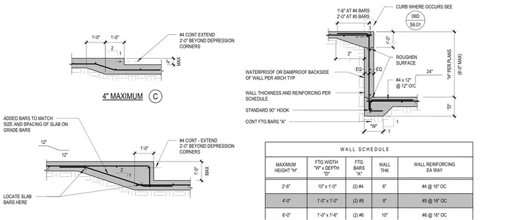
Slab-on-grade elevation changes and depressions feature associated continuous wall footings. The assembly incorporates continuous number four reinforcing bars extending two feet beyond depression corners, with added bars matching the size and spacing of the main slab-on-grade reinforcement. Wall thickness, footing dimensions, and reinforcing sizes vary according to the accompanying wall schedule based on a maximum height of six feet. The backside of the concrete wall receives waterproofing or dampproofing per architectural specifications, and cold joints feature roughened surfaces.
4" MAXIMUM C W A L L S C H E D U L E 2 1 #4 CONT EXTEND 2'-0" BEYOND DEPRESSION CORNERS 2 1 #4 CONT - EXTEND 2'-0" BEYOND DEPRESSION CORNERS ADDED BARS TO MATCH SIZE AND SPACING OF SLAB ON GRADE BARS 12" 12" LOCATE SLAB BARS HERE STANDARD 90° HOOK 1 1 #4 x 12" @ 12" O/C 24" WALL THICKNESS AND REINFORCING PER SCHEDULE CURB WHERE OCCURS SEE WATERPROOF OR DAMPROOF BACKSIDE OF WALL PER ARCH TYP CONT FTG BARS "A" #5 @ 16" OC 4'-0" (2) #5 1'-0" x 1'-0" MAXIMUM HEIGHT "H" FTG BARS "A" FTG WIDTH "W" x DEPTH "D" WALL REINFORCING EA WAY 8" WALL THK ROUGHEN SURFACE #4 @ 16" OC 2'-6" (2) #4 6" 10" x 1'-0" 1'-6" AT #4 BARS 2'-0" AT #5 BARS MAX 4" 1'-0" 1'-0" MAX 1'-0" 1'-0" 2" EQ EQ 1'-0'' "D" (6'-0'' MAX) "H" PER PLANS 06D S6.01 #6 @ 16" OC 6'-0" (2) #6 1'-0" x 1'-6" 10" "W"
Members view this detail in full resolution, download the CAD files (SVG, PDF), and can adapt it in the built-in CAD editor — export DXF, DWG, or PDF.
Start membership