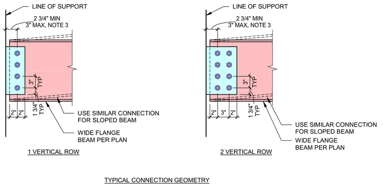
Typical connection geometry for wide flange steel beams framing into a line of support, showing single and double vertical row fastener configurations with specified edge distances and bolt spacings. The layout indicates a minimum two and three-quarter inch and maximum three-inch spacing from the support line, with one and three-quarter inch typical spacing from the beam flanges. Similar connection geometry applies for sloped beams sized per plan.
2" 2" TYP 1 3/4" TYP 3" 3" MAX, NOTE 3 2 3/4" MIN USE SIMILAR CONNECTION FOR SLOPED BEAM WIDE FLANGE BEAM PER PLAN 2" 3" 2" TYP 1 3/4" TYP 3" 3" MAX, NOTE 3 2 3/4" MIN USE SIMILAR CONNECTION FOR SLOPED BEAM WIDE FLANGE BEAM PER PLAN 1 VERTICAL ROW 2 VERTICAL ROW TYPICAL CONNECTION GEOMETRY LINE OF SUPPORT LINE OF SUPPORT
Members view this detail in full resolution, download the CAD files (SVG, PDF), and can adapt it in the built-in CAD editor — export DXF, DWG, or PDF.
Start membership