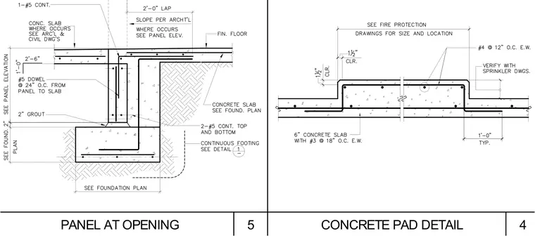
A six-inch concrete slab is reinforced with number three bars at eighteen inches on center each way, featuring a dropped pad section defined by number four bars at twelve inches on center each way with one and a half inch clear spacing. The assembly connects to a continuous concrete footing with two number five continuous top and bottom bars, supported by a two-inch grout layer and number five dowels at twenty-four inches on center from the panel to the slab. Additional continuity is provided by a one number five continuous bar with a two-foot lap length, sloping per architectural requirements where indicated. Fire protection sizing and locations are verified per separate drawings, with sprinkler drawing coordination required.
Members view this detail in full resolution, download the CAD files (SVG, PDF), and can adapt it in the built-in CAD editor — export DXF, DWG, or PDF.
Start membership