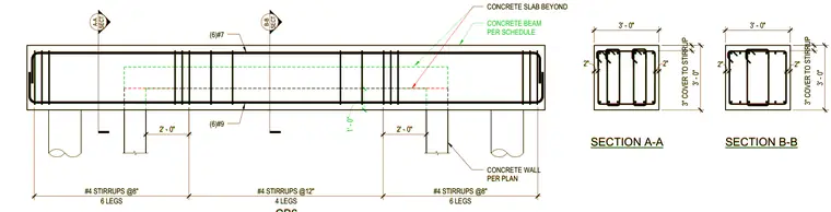
A concrete beam elevation and two cross sections, designated as section A-A and section B-B, are supported by concrete walls per plan with a concrete slab beyond. The beam measures three feet by three feet with a three-inch cover to the stirrups. The bottom longitudinal reinforcement consists of six number nine bars, while the top reinforcement includes six number seven bars. Shear reinforcement varies along the span, utilizing six legs of number four stirrups at eight inches on center at the ends and four legs of number four stirrups at twelve inches on center in the middle zone.
SECT A-A SECT B-B 3" COVER TO STIRRUP 3' - 0" 2" 3' - 0" 3' - 0" 3' - 0" 2" 2" 2" 3" COVER TO STIRRUP SECTION B-B SECTION A-A (6)#9 (6)#7 6 LEGS #4 STIRRUPS @8" 4 LEGS #4 STIRRUPS @12" 6 LEGS #4 STIRRUPS @8" 2' - 0" 2' - 0" CONCRETE WALL PER PLAN CONCRETE SLAB BEYOND SECT A-A SECT B-B 3" COVER TO STIRRUP 3' - 0" 2" 3' - 0" 3' - 0" 3' - 0" 2" 2" 2" 3" COVER TO STIRRUP SECTION B-B SECTION A-A (6)#9 (6)#7 1' - 0" 6 LEGS #4 STIRRUPS @8" 4 LEGS #4 STIRRUPS @12" 6 LEGS #4 STIRRUPS @8" 2' - 0" 2' - 0" CONCRETE BEAM PER SCHEDULE CONCRETE WALL PER PLAN CONCRETE SLAB BEYOND
Members view this detail in full resolution, download the CAD files (SVG, PDF), and can adapt it in the built-in CAD editor — export DXF, DWG, or PDF.
Start membership