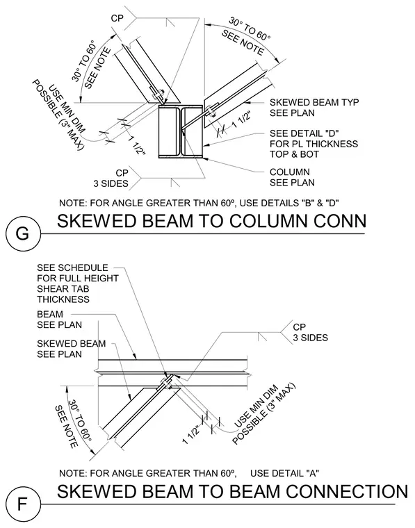
A skewed beam connects to a supporting column web or flange using a single plate or shear tab detailed per schedule. The framing angle ranges from thirty to sixty degrees, with one and one half inch clearances and specific edge dimensions noted. Additional notes direct the user to alternate details when angles exceed sixty degrees. A companion detail shows a skewed beam framing into another beam using similar bolted connection geometry and weld specifications.
SKEWED BEAM TO BEAM CONNECTION F SKEWED BEAM SEE PLAN BEAM SEE PLAN 1 1/2" CP 3 SIDES POSSIBLE (3" MAX) USE MIN DIM SEE SCHEDULE FOR FULL HEIGHT SHEAR TAB THICKNESS SKEWED BEAM TO COLUMN CONN G 1 1/2" CP SKEWED BEAM TYP SEE PLAN COLUMN SEE PLAN SEE DETAIL "D" FOR PL THICKNESS TOP & BOT 1 1/2" POSSIBLE (3" MAX) USE MIN DIM SEE NOTE 30° TO 60° SEE NOTE 30° TO 60° CP 3 SIDES NOTE: FOR ANGLE GREATER THAN 60º, USE DETAILS "B" & "D" NOTE: FOR ANGLE GREATER THAN 60º, USE DETAIL "A" SEE NOTE 30° TO 60°
Members view this detail in full resolution, download the CAD files (SVG, PDF), and can adapt it in the built-in CAD editor — export DXF, DWG, or PDF.
Start membership