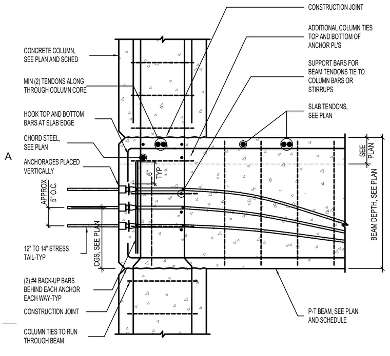
A post-tensioned concrete beam frames into a reinforced concrete column with continuous column ties running through the joint. Additional column ties are placed at the top and bottom of the anchor plates. Vertical anchorages are spaced approximately five inches on center with twelve to fourteen inch stress tails. Two number four backup bars are placed behind each anchor in each direction typically. Support bars for beam tendons tie directly to column vertical bars or stirrups. Top and bottom reinforcing bars hook at the slab edge alongside chord steel and slab tendons sized per plan.
CONCRETE COLUMN, SEE PLAN AND SCHED P-T BEAM, SEE PLAN COLUMN TIES TO RUN THROUGH BEAM ADDITIONAL COLUMN TIES TOP AND BOTTOM OF ANCHOR PL'S ANCHORAGES PLACED VERTICALLY SUPPORT BARS FOR BEAM TENDONS TIE TO COLUMN BARS OR STIRRUPS 12" TO 14" STRESS TAIL-TYP (2) #4 BACK-UP BARS BEHIND EACH ANCHOR EACH WAY-TYP HOOK TOP AND BOTTOM BARS AT SLAB EDGE MIN (2) TENDONS ALONG THROUGH COLUMN CORE SLAB TENDONS, SEE PLAN CONSTRUCTION JOINT AND SCHEDULE CHORD STEEL, SEE PLAN CONSTRUCTION JOINT 6" TYP APPROX 5" O.C. SEE PLAN BEAM DEPTH, SEE PLAN CGS, SEE PLAN A
Members view this detail in full resolution, download the CAD files (SVG, PDF), and can adapt it in the built-in CAD editor — export DXF, DWG, or PDF.
Start membership