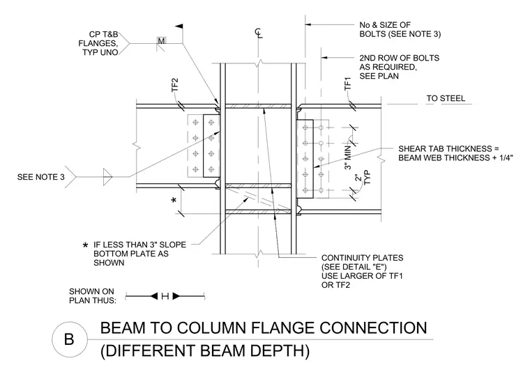
A beam-to-column flange connection joins steel beams of differing depths to a common column. The connection utilizes welded shear tabs at the beam webs, with shear tab thickness sized at the beam web thickness plus one-quarter inch. Continuity plates are provided at the top and bottom flanges, utilizing the larger thickness of either flange TF1 or TF2. Additional bolt sizing and second row requirements are sized per plan, maintaining a three-inch minimum typical spacing. A sloped bottom plate is installed when the slope is less than three inches.
BEAM TO COLUMN FLANGE CONNECTION (DIFFERENT BEAM DEPTH) B TO STEEL No & SIZE OF BOLTS (SEE NOTE 3) 2ND ROW OF BOLTS AS REQUIRED, SEE PLAN IF LESS THAN 3" SLOPE BOTTOM PLATE AS SHOWN CONTINUITY PLATES (SEE DETAIL "E") USE LARGER OF TF1 OR TF2 SHEAR TAB THICKNESS = BEAM WEB THICKNESS + 1/4" * SHOWN ON PLAN THUS: * 3" MIN TYP 2" TF2 TF1 CP T&B FLANGES, TYP UNO M SEE NOTE 3
Members view this detail in full resolution, download the CAD files (SVG, PDF), and can adapt it in the built-in CAD editor — export DXF, DWG, or PDF.
Start membership