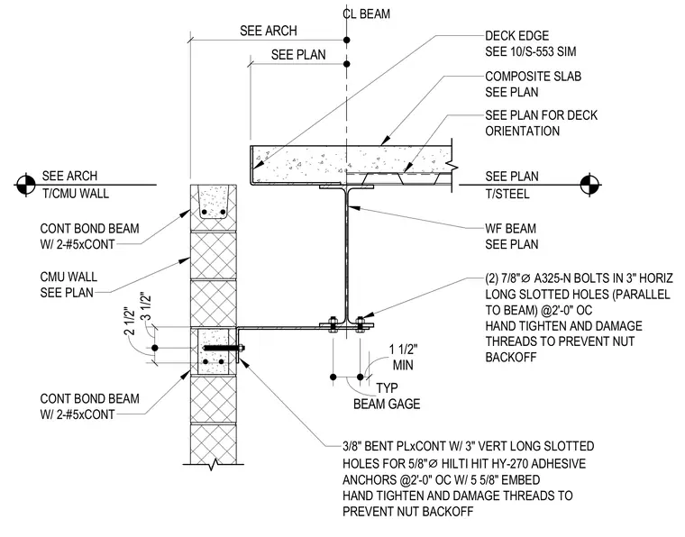
A composite slab is supported by a wide-flange steel beam that connects back to a concrete masonry unit wall. A continuous three-eighths-inch bent plate anchors into the masonry bond beam using five-eighths-inch diameter adhesive anchors spaced at two feet on center with five and five-eighths inches of embedment, featuring hand-tightened nuts with damaged threads to prevent backoff. The wide-flange beam flange fastens to the bent plate using two seven-eighths-inch diameter A325-N bolts placed in three-inch horizontal long slotted holes parallel to the beam, spaced at two feet on center, also hand-tightened with damaged threads. The CMU wall incorporates continuous bond beams reinforced with two number five continuous bars. The composite slab sits atop the steel beam and deck, with deck orientation and top of steel elevations sized per plan.
2 1/2" 3 1/2" COMPOSITE SLAB SEE PLAN (2) 7/8" ⌀ A325-N BOLTS IN 3" HORIZ LONG SLOTTED HOLES (PARALLEL TO BEAM) @2'-0" OC HAND TIGHTEN AND DAMAGE THREADS TO PREVENT NUT BACKOFF WF BEAM SEE PLAN 3/8" BENT PLxCONT W/ 3" VERT LONG SLOTTED HOLES FOR 5/8" ⌀ HILTI HIT HY-270 ADHESIVE ANCHORS @2'-0" OC W/ 5 5/8" EMBED HAND TIGHTEN AND DAMAGE THREADS TO PREVENT NUT BACKOFF CONT BOND BEAM W/ 2-#5xCONT CMU WALL SEE PLAN CL BEAM DECK EDGE SEE 10/S-553 SIM T/CMU WALL SEE ARCH CONT BOND BEAM W/ 2-#5xCONT BEAM GAGE TYP MIN 1 1/2" SEE PLAN FOR DECK ORIENTATION SEE ARCH SEE PLAN T/STEEL SEE PLAN
Members view this detail in full resolution, download the CAD files (SVG, PDF), and can adapt it in the built-in CAD editor — export DXF, DWG, or PDF.
Start membership