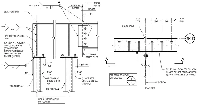
A steel beam frames into the top of a column, featuring a column cap plate sized to match the beam or column width with a minimum thickness equal to the beam flange. Three-eighths-inch thick stiffener plates are welded to each side of the beam web using three-sixteenths-inch fillet welds. A half-inch thick by twelve-inch splice plate is connected to each side using four three-quarter-inch diameter A307 bolts at standard gauge. The assembly incorporates a one-half-inch gap and a plate with nine three-quarter-inch diameter welded stud anchors at a seven-inch gauge on each side of the panel. Field welds are specified at one-quarter-inch on near side and far side.
GRID 4 1/2" 7" 7" 2 1/2" PANEL JOINT CL OF BEAM PL 1/2"x1'-8" x BEAM DEPTH + 4" W/ (9) 3/4"Ø WELDED STUD ANCHORS @ 7" GA (TYP EA SIDE OF PANEL) FOR ITEMS NOT SHOWN OR NOTED SEE 18 - TYP TYP TYP TYP PLAN VIEW A PER PLAN 1'-6" MIN 1 1/2" TYP 1/2" 1 1/2" TYP 1/2" GAP 1 1/2" TYP 1 1/2" TYP 3/8" STIFF PL EA SIDE, TYP COL CAP PL x BM WIDTH OR COL WIDTH +1/2" (WHICHEVER IS GREATER) AND SAME THICKNESS AS BM FLANGE (3/4" MIN) NOT ALL ITEMS SHOWN FOR CLARITY (2) 3/4"Ø A307 BOLTS @ STD GA (2) 3/4"Ø A307 BOLTS @ STD GA (4 TOTAL) 1/2" THKx12" SPLICE PL ES COL PER PLAN COL PER PLAN BEAM PER PLAN 1 3/4" 3/16 TYP 1/4 N.S. & F.S. 1/4 TYP BOLTS PER 18/-
Members view this detail in full resolution, download the CAD files (SVG, PDF), and can adapt it in the built-in CAD editor — export DXF, DWG, or PDF.
Start membership