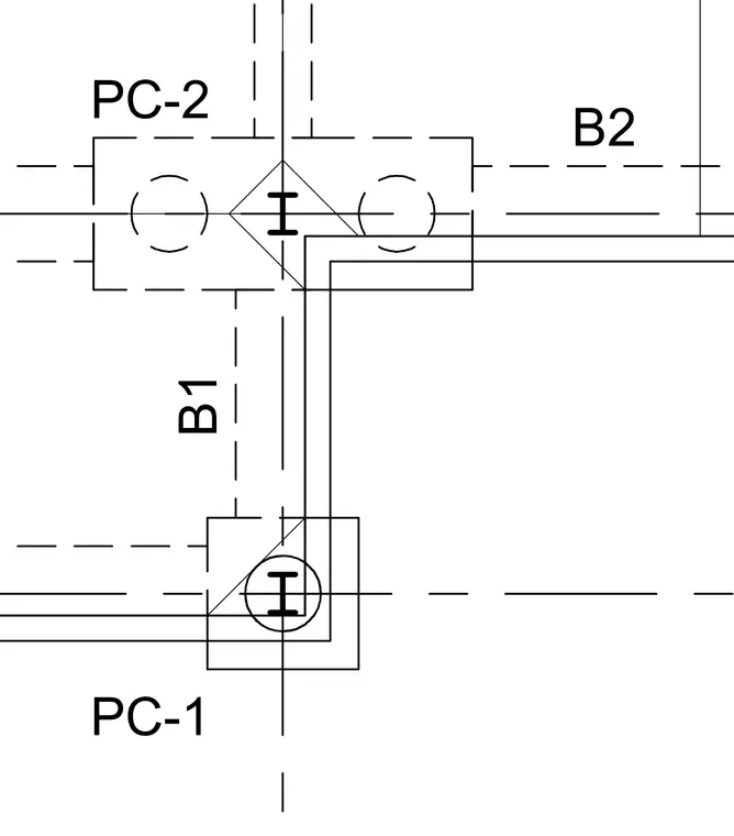
A structural framing connection layout incorporates steel columns, beams, and connection elements designated as B1, B2, PC-1, and PC-2. Dashed centerlines align the structural grid for the intersecting members. Solid lines indicate intersecting wall or edge assemblies relative to the column centerlines.
Members view this detail in full resolution, download the CAD files (SVG, PDF), and can adapt it in the built-in CAD editor — export DXF, DWG, or PDF.
Start membership