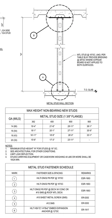
A non-bearing cold-formed metal stud wall framing assembly extends between concrete slabs or metal decks. The metal studs are spaced at sixteen inches on center and require bridging at forty-eight inches on center where gypsum board is omitted from either surface. Height limitations based on stud gauge and size are included, along with a complete fastener schedule specifying approved anchors, screws, and spacing.
3/4" "H" METAL STUD WALL SECTION B A STUD PARALLEL TO STEEL NOTES: 1. MAXIMUM STUD HEIGHT "H" FOR STUDS @ 16" OC. 2. SEE ARCHITECTURAL FOR OTHER CONDITIONS. 3. LIMIT L/240 DEFLECTION. 4. STUDS CARRYING EQUIPMENT OR CASEWORK WEIGHING 40 LBS OR MORE SHALL BE 16GA MIN. EA SIDE EA STUD MTL STUD @ 16"OC, UNO, PER TABLE BLW. PROVIDE BRIDGING @ 48"OC WHERE GYPSUM BOARD IS NOT APPLIED TO BOTH SURFACES. T.O. SLAB MAX HEIGHT NON-BEARING NEW STUDS GA (MILS) METAL STUD SIZE (1 3/8" FLANGE) 362 400 600 800 19'-4" 21'-6" 29'-11" 38'-1" 18'-1" 20'-1" 27'-11" 35'-6" 16'-11" 18'-9" 26'-0" 33'-1" 15'-6" 17'-3" 23'-11" - 6 5 4 3 2 1 HILTI KB-TZ 1/4"Øx2" EMBED EXPANSION ANCHOR @ 12"OC HILTI DNI32 P8 PDF @ DECK W/ CONC OR #10 SMS @ ROOF MTL DECK HILTI DNI32 P8 PDF @ 16"OC HILTI DNI32 P8 PDF @ 16"OC #10 SHEET METAL SCREW (SMS) #12 SMS FASTENER SIZE & SPACING MARK REMARKS ESR-1663 ESR-1663 ESR-1663 ER-5202 ER-5202 ER-1917 METAL STUD FASTENER SCHEDULE 14 (68) 16 (54) 18 (43) 20 (33)
Members view this detail in full resolution, download the CAD files (SVG, PDF), and can adapt it in the built-in CAD editor — export DXF, DWG, or PDF.
Start membership