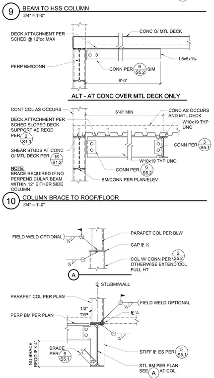
These structural details illustrate beam-to-HSS column framing connections, column lateral bracing conditions, and parapet support assemblies. The details feature W10x19 framing members, angle connections, plate stiffeners, and optional field welds. Concrete over metal deck assemblies tie into the steel framing with specified deck attachments and shear studs. Lateral bracing requirements are indicated based on proximity to perpendicular beams.
BM/CONN PER PLAN/ELEV CONT COL AS OCCURS W10x19 TYP UNO CONN PER W10x19 TYP UNO NOTE: BRACE REQUIRED IF NO PERPENDICULAR BEAM WITHIN 12" EITHER SIDE COLUMN CONN PER PERP BM/CONN L5x5xÌ CONC O/ MTL DECK 6'-0" 6'-0" MIN 6 S5.2 ___________ 3 S5.1 ___________ DECK ATTACHMENT PER SCHED SLOPED DECK SUPPORT AS REQD PER CONC AS OCCURS AND MTL DECK DECK ATTACHMENT PER SCHED @ 12"oc MAX CONN PER SIM 6 S5.2 ___________ ALT - AT CONC OVER MTL DECK ONLY SHEAR STUDS AT CONC O/ MTL DECK PER 16 S1.2 ___________ 2 S1.3 ___________ ¢ STL/BM/WALL PARAPET COL PER PLAN £Ë STIFF £ ES PER STL BM PER PLAN SEE AT COL PERP BM PER PLAN A PARAPET COL PER BLW A COL W/ CONN PER OTHERWISE EXTEND COL FULL HT CAP £Ï Ë Ë FIELD WELD OPTIONAL TYP 1/2" Ë FIELD WELD OPTIONAL Ë 5 S5.1 ___________ 2 S5.2 NO BRACE REQD IF Ä 4" BRACE PER 9 S5.1 3/4" = 1'-0" 10 COLUMN BRACE TO ROOF/FLOOR 3/4" = 1'-0" 9 BEAM TO HSS COLUMN
Members view this detail in full resolution, download the CAD files (SVG, PDF), and can adapt it in the built-in CAD editor — export DXF, DWG, or PDF.
Start membership