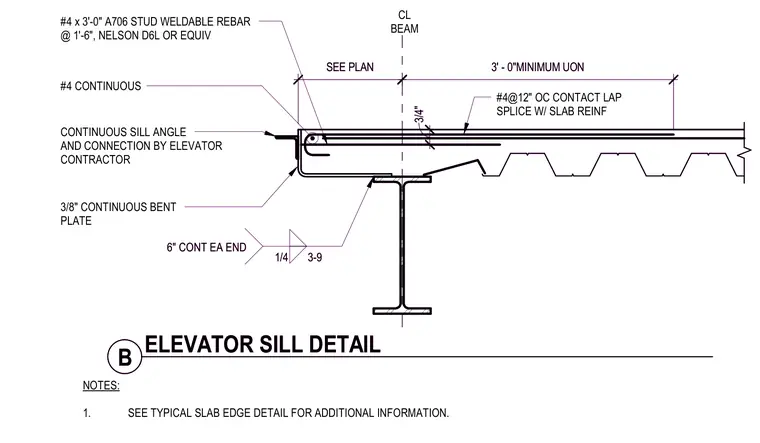
An elevator sill assembly at a concrete slab edge is supported by a structural steel beam. A three-eighths-inch continuous bent plate extends along the slab edge, welded to the supporting steel beam with a one-quarter-inch fillet weld six inches long at each end. A continuous sill angle and connection are provided by the elevator contractor. Reinforcement includes number-four continuous rebar, number-four by three-foot-long A706 stud weldable rebar spaced at one foot six inches on center with Nelson D6L or equivalent studs, and number-four rebar at twelve inches on center for contact lap splicing with slab reinforcement.
NOTES: 1. SEE TYPICAL SLAB EDGE DETAIL FOR ADDITIONAL INFORMATION. #4 x 3'-0" A706 STUD WELDABLE REBAR @ 1'-6", NELSON D6L OR EQUIV 3/8" CONTINUOUS BENT PLATE CONTINUOUS SILL ANGLE AND CONNECTION BY ELEVATOR CONTRACTOR CL BEAM SEE PLAN 3/4" 3' - 0"MINIMUM UON #4@12" OC CONTACT LAP SPLICE W/ SLAB REINF #4 CONTINUOUS 1/4 3-9 6" CONT EA END B ELEVATOR SILL DETAIL NOTES: 1. SEE TYPICAL SLAB EDGE DETAIL FOR ADDITIONAL INFORMATION. #4 x 3'-0" A706 STUD WELDABLE REBAR @ 1'-6", NELSON D6L OR EQUIV 3/8" CONTINUOUS BENT PLATE CONTINUOUS SILL ANGLE AND CONNECTION BY ELEVATOR CONTRACTOR CL BEAM SEE PLAN 3/4" 3' - 0"MINIMUM UON #4@12" OC CONTACT LAP SPLICE W/ SLAB REINF #4 CONTINUOUS 1/4 3-9 6" CONT EA END B ELEVATOR SILL DETAIL
Members view this detail in full resolution, download the CAD files (SVG, PDF), and can adapt it in the built-in CAD editor — export DXF, DWG, or PDF.
Start membership