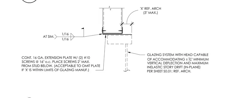
A head support connection for a glazing system accommodates plus or minus three-quarters of an inch of minimum vertical deflection and maximum in-plane inelastic story drift per sheet S0.01. A continuous 16-gauge extension plate is fastened with two number 10 screws at 16 inches on center, placed a maximum of 2 inches from the stud below. The extension plate is acceptable to omit if dimension 'X' is within the limits of the glazing manufacturer, referencing architectural drawings with a 3-inch maximum at similar conditions.
GLAZING SYSTEM WITH HEAD CAPABLE OF ACCOMMODATING ± 3 4 " MINIMUM VERTICAL DEFLECTION AND MAXIMUM INELASTIC STORY DRIFT (IN-PLANE) PER SHEET S0.01; REF. ARCH. 'X' REF. ARCH (3" MAX.) AT SIM. 1/16 1/16 CONT. 16 GA. EXTENSION PLATE W/ (2) #10 SCREWS @ 16" o.c. PLACE SCREWS 2" MAX. FROM STUD BELOW. (ACCEPTABLE TO OMIT PLATE IF 'X' IS WITHIN LIMITS OF GLAZING MANUF.)
Members view this detail in full resolution, download the CAD files (SVG, PDF), and can adapt it in the built-in CAD editor — export DXF, DWG, or PDF.
Start membership