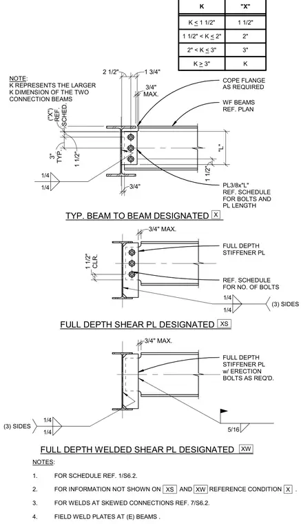
Structural steel beam-to-beam framing connections using wide flange beams. The standard connection utilizes a three-eighths inch thick shear plate welded to the supporting member and bolted to the supported beam web, with the supported beam flange coped as required and maintained with a three-quarter inch maximum clearance. Alternative configurations include full depth shear plates and full depth welded shear plates with stiffener plates and optional erection bolts. Fillet welds of one-quarter inch and five-sixteenth inch sizes are specified on multiple sides as indicated by the weld symbols. A design table coordinates dimension X with the K dimension of the connecting beams.
TYP. BEAM TO BEAM DESIGNATED NOTE: K REPRESENTS THE LARGER K DIMENSION OF THE TWO CONNECTION BEAMS COPE FLANGE AS REQUIRED WF BEAMS REF. PLAN PL3/8x"L" REF. SCHEDULE FOR BOLTS AND PL LENGTH X SCHED. ("X") REF. MAX. 3/4" FULL DEPTH STIFFENER PL FULL DEPTH SHEAR PL DESIGNATED FULL DEPTH STIFFENER PL w/ ERECTION BOLTS AS REQ'D. XS FULL DEPTH WELDED SHEAR PL DESIGNATED XW 5/16 1/4 1/4 (3) SIDES 1/4 1/4 (3) SIDES 1/4 1/4 CLR. 1 1/2" "L" 2 1/2" 1 3/4" 1 1/2" 1 1/2" TYP. 3" 3/4" NOTES: 1. FOR SCHEDULE REF. 1/S6.2. 2. FOR INFORMATION NOT SHOWN ON AND REFERENCE CONDITION . 3. FOR WELDS AT SKEWED CONNECTIONS REF. 7/S6.2. 4. FIELD WELD PLATES AT (E) BEAMS . X XS XW K < 1 1/2" 1 1/2" K "X" 1 1/2" < K < 2" 2" 2" < K < 3" 3" K > 3" K 3/4" MAX. 3/4" MAX. REF. SCHEDULE FOR NO. OF BOLTS
Members view this detail in full resolution, download the CAD files (SVG, PDF), and can adapt it in the built-in CAD editor — export DXF, DWG, or PDF.
Start membership