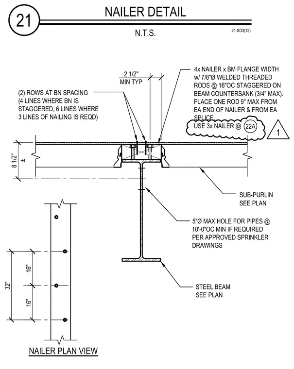
A wood nailer matching the steel beam flange width is fastened to the structural steel beam using seven-eighths-inch diameter welded threaded rods spaced at sixteen inches on center and staggered with a maximum three-quarter-inch countersink. A single rod is positioned within nine inches maximum from each end of the nailer and from each splice, utilizing either a four-by or three-by nailer dimensioned per plan. The assembly accommodates sub-purlins sized per plan and permits five-inch maximum diameter holes for pipes spaced at ten feet on center minimum when required by approved sprinkler drawings.
4x NAILER x BM FLANGE WIDTH w/ 7/8"Ø WELDED THREADED RODS @ 16"OC STAGGERED ON BEAM COUNTERSANK (3/4" MAX). PLACE ONE ROD 9" MAX FROM EA END OF NAILER & FROM EA SPLICE. USE 3x NAILER @ 21 NAILER DETAIL N.T.S. 21-SD3(12) 5"Ø MAX HOLE FOR PIPES @ 10'-0"OC MIN IF REQUIRED PER APPROVED SPRINKLER DRAWINGS SUB-PURLIN SEE PLAN 8 1/2" ± STEEL BEAM SEE PLAN 16" 16" 32" NAILER PLAN VIEW (2) ROWS AT BN SPACING (4 LINES WHERE BN IS STAGGERED, 6 LINES WHERE 3 LINES OF NAILING IS REQD) 2 1/2" MIN TYP 22A 1
Members view this detail in full resolution, download the CAD files (SVG, PDF), and can adapt it in the built-in CAD editor — export DXF, DWG, or PDF.
Start membership