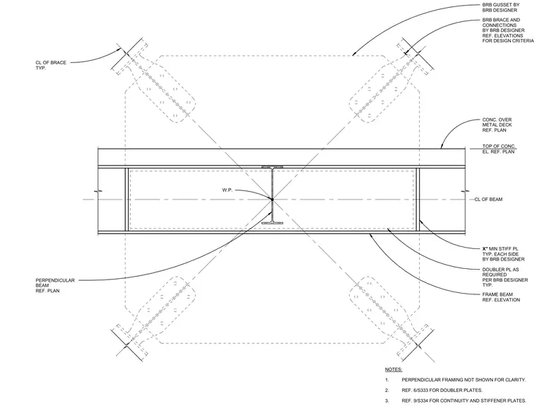
A buckling-restrained brace X-joint connection occurs at a structural steel frame beam with a concrete over metal deck floor slab. Four diagonal buckling-restrained braces intersect at a common work point on the centerline of the beam, with braces, gusset plates, and connections provided by the specialty buckling-restrained brace designer. Minimum-thickness stiffener plates are positioned on each side of the beam web alongside doubler plates as required by the specialty designer. Perpendicular framing is omitted for clarity, with references provided to specific sheets for doubler plates, continuity plates, and stiffener plates.
TOP OF CONC. EL. REF. PLAN CONC. OVER METAL DECK REF. PLAN CL OF BRACE TYP. W.P. CL OF BEAM BRB BRACE AND CONNECTIONS BY BRB DESIGNER REF. ELEVATIONS FOR DESIGN CRITERIA FRAME BEAM REF. ELEVATION DOUBLER PL AS REQUIRED PER BRB DESIGNER TYP. X" MIN STIFF PL TYP. EACH SIDE BY BRB DESIGNER PERPENDICULAR BEAM REF. PLAN NOTES: 1. PERPENDICULAR FRAMING NOT SHOWN FOR CLARITY. 2. REF. 6/S333 FOR DOUBLER PLATES. 3. REF. 9/S334 FOR CONTINUITY AND STIFFENER PLATES. BRB GUSSET BY BRB DESIGNER
Members view this detail in full resolution, download the CAD files (SVG, PDF), and can adapt it in the built-in CAD editor — export DXF, DWG, or PDF.
Start membership