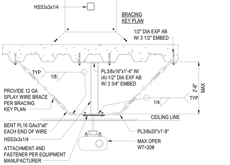
Suspended equipment with a maximum operating weight of twenty pounds hangs from a vertical hollow structural section measuring three by three inches by one-quarter inch thick. This structural steel tube welds to a three-eighths by sixteen-inch by one-foot four-inch base plate fastened to the underside of a concrete on metal deck using four one-half-inch diameter expansion anchors with three and three-quarters inch embedment. Diagonal twelve-gauge splay wire braces extend from bent sixteen-gauge plates measuring three by six inches at each end of the wire to three-eighths by twenty-inch by one-foot eight-inch plates welded to the structural framing. Additional one-half-inch diameter expansion anchors with three and one-half inch embedment secure the bracing elements directly into the concrete deck. Attachment and fastener details for the equipment itself follow the manufacturer specifications.
CEILING LINE BENT PL16 GAx3"x6" EACH END OF WIRE PROVIDE 12 GA SPLAY WIRE BRACE PER BRACING KEY PLAN PL3/8x20"x1'-8" HSS3x3x1/4 PL3/8x16"x1'-4" W/ (4)-1/2" DIA EXP AB W/ 3 3/4" EMBED BRACING KEY PLAN HSS3x3x1/4 MAX OPER WT=20# 1/2" DIA EXP AB W/ 3 1/2" EMBED 1/4 TYP 1/8 TYP MAX 2'-6" ATTACHMENT AND FASTENER PER EQUIPMENT MANUFACTURER
Members view this detail in full resolution, download the CAD files (SVG, PDF), and can adapt it in the built-in CAD editor — export DXF, DWG, or PDF.
Start membership