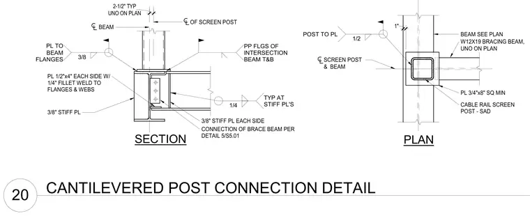
A cable rail screen post connects to a supporting steel beam using three-eighths-inch stiffener plates welded to the beam flanges with three-eighths-inch welds. One-half-inch by four-inch plates are provided on each side with one-quarter-inch fillet welds to the flanges and webs. A W12x19 bracing beam intersects the assembly with three-eighths-inch stiffener plates on each side and is connected via a brace beam per detail 5/S5.01. A square plate measuring three-fourths-inch by eight inches minimum ties the screen post and beam together.
CABLE RAIL SCREEN POST - SAD PLAN 3/8" STIFF PL PL 1/2"x4" EACH SIDE W/ 1/4" FILLET WELD TO FLANGES & WEBS BEAM 3/8" STIFF PL EACH SIDE OF SCREEN POST PL 3/4"x8" SQ MIN SCREEN POST & BEAM BEAM SEE PLAN UNO ON PLAN 2-1/2" TYP PP FLGS OF INTERSECTION BEAM T&B 1/4 TYP AT STIFF PL'S 1" SECTION W12X19 BRACING BEAM, UNO ON PLAN 3/8 PL TO BEAM FLANGES 1/2 POST TO PL CONNECTION OF BRACE BEAM PER DETAIL 5/S5.01 20 CANTILEVERED POST CONNECTION DETAIL
Members view this detail in full resolution, download the CAD files (SVG, PDF), and can adapt it in the built-in CAD editor — export DXF, DWG, or PDF.
Start membership