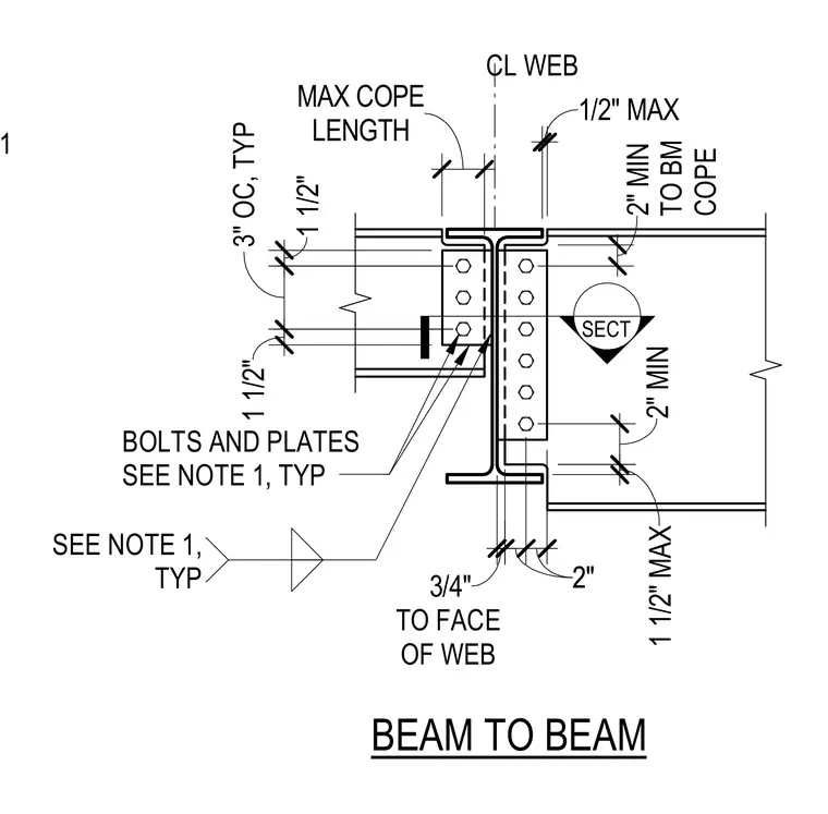
A secondary steel beam frames into the web of a primary supporting beam utilizing connecting plates and bolts. The supported beam features a coped top flange to clear the flange of the supporting beam, maintaining a maximum cope length with specified clearances to the face of the web. Three-quarter-inch bolts and connection plates are spaced at three inches on center typically. Dimensions govern the minimum and maximum distances from the top of the beam to the cope, as well as offsets to the centerline of the web.
SECT SEE NOTE 1 1/2" MAX 3/4" BOLTS AND PLATES SEE NOTE 1, TYP SEE NOTE 1, TYP TO BM COPE LENGTH MAX COPE CL WEB BEAM TO BEAM TO FACE OF WEB 1 1/2" MAX 2" MIN 2"2" 2" MIN 3" OC, TYP 6" 1 1/2" 1 1/2"
Members view this detail in full resolution, download the CAD files (SVG, PDF), and can adapt it in the built-in CAD editor — export DXF, DWG, or PDF.
Start membership