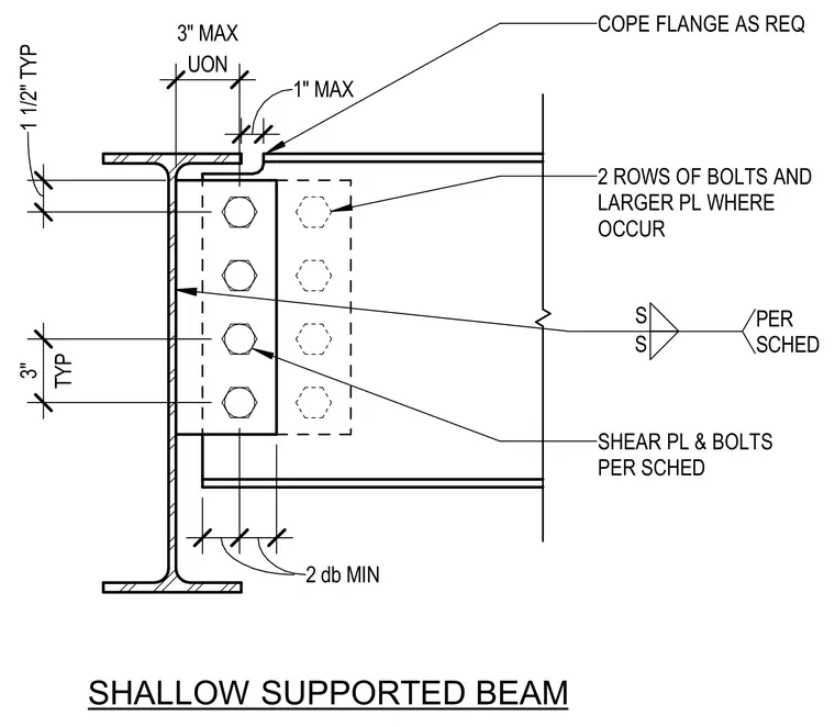
A supported steel beam frames into a supporting structural steel member with a welded shear plate and two rows of high-strength bolts. The top flange of the supported beam is coped as required, maintaining a maximum one-inch clearance from the support unless otherwise noted. Edge distances and bolt spacings follow standard configurations, including a one-and-a-half-inch typical dimension and a minimum of two bolt diameters. Larger plates and additional bolt rows are utilized where specified by the schedule. The shear plate is welded to the support with fillet welds sized per the structural schedule.
COPE FLANGE AS REQ 2 ROWS OF BOLTS AND LARGER PL WHERE OCCUR SHEAR PL & BOLTS PER SCHED UON 3" MAX TYP 3" 2 db MIN 1 1/2" TYP S S PER SCHED SHALLOW SUPPORTED BEAM 1" MAX
Members view this detail in full resolution, download the CAD files (SVG, PDF), and can adapt it in the built-in CAD editor — export DXF, DWG, or PDF.
Start membership