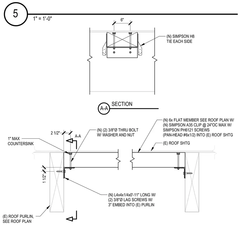
An antenna support assembly is attached to an existing wood roof structure. A new flat member is anchored to the existing roof sheathing using Simpson A35 clips spaced at twenty-four inches on center maximum, secured with Simpson pan-head screws. Simpson H8 ties are installed on each side of the framing. The new steel angle, sized as L4x4x1/4 by zero feet eleven inches long, connects to the existing roof purlin using two three-eighths-inch diameter lag screws with a three-inch embedment. Two three-eighths-inch diameter through-bolts with washers and nuts secure the flat member to the supporting angle, featuring a one-inch maximum countersink.
A-A SECTION A-A (N) SIMPSON H8 TIE EACH SIDE 6" (E) ROOF SHTG (N) 6x FLAT MEMBER SEE ROOF PLAN W/ (N) SIMPSON A35 CLIP @ 24"OC MAX W/ SIMPSON PH6121 SCREWS (PAN-HEAD #6x1/2) INTO (E) ROOF SHTG (N) (2) 3/8"Ø THRU BOLT W/ WASHER AND NUT 2 1/2" 1" MAX COUNTERSINK (E) ROOF PURLIN, SEE ROOF PLAN (N) L4x4x1/4x0'-11" LONG W/ (2) 3/8"Ø LAG SCREWS W/ 3" EMBED INTO (E) PURLIN 1 1/2" 1" = 1'-0" 5
Members view this detail in full resolution, download the CAD files (SVG, PDF), and can adapt it in the built-in CAD editor — export DXF, DWG, or PDF.
Start membership