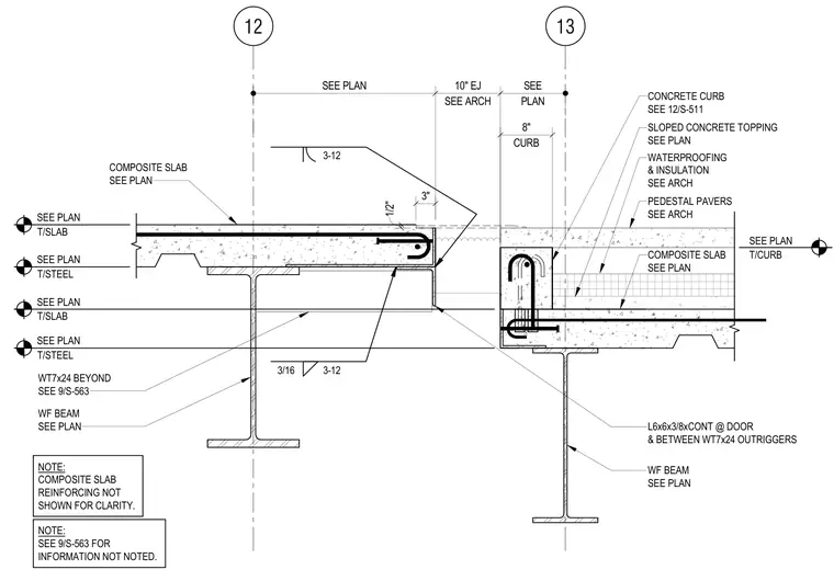
A floor expansion joint assembly bridges two composite floor slabs supported by wide-flange steel beams. The ten-inch expansion joint incorporates a continuous L6x6x3/8 angle located at the door and between WT7x24 outriggers, welded with a three-sixteenths inch fillet weld at twelve inches on center. The assembly features an eight-inch concrete curb with sloped concrete topping, waterproofing, insulation, and pedestal pavers on one side, while the adjacent side carries a composite slab on a wide-flange beam with top of slab and top of steel elevations sized per plan. Composite slab reinforcing is omitted for clarity, and secondary framing members such as WT7x24 outriggers are referenced to another detail.
12 13 SEE PLAN SEE ARCH 10" EJ PLAN SEE CURB 8" CONCRETE CURB SEE 12/S-511 SLOPED CONCRETE TOPPING SEE PLAN WATERPROOFING & INSULATION SEE ARCH PEDESTAL PAVERS SEE ARCH COMPOSITE SLAB SEE PLAN L6x6x3/8xCONT @ DOOR & BETWEEN WT7x24 OUTRIGGERS WF BEAM SEE PLAN WF BEAM SEE PLAN NOTE: COMPOSITE SLAB REINFORCING NOT SHOWN FOR CLARITY. NOTE: SEE 9/S-563 FOR INFORMATION NOT NOTED. WT7x24 BEYOND SEE 9/S-563 T/SLAB SEE PLAN T/STEEL SEE PLAN T/SLAB SEE PLAN T/STEEL SEE PLAN COMPOSITE SLAB SEE PLAN 3/16 3-12 3-12 3" 1/2" T/CURB SEE PLAN
Members view this detail in full resolution, download the CAD files (SVG, PDF), and can adapt it in the built-in CAD editor — export DXF, DWG, or PDF.
Start membership