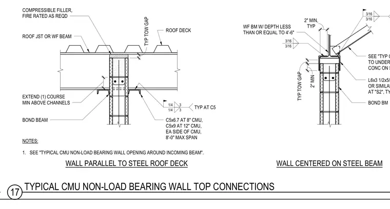
Top-of-wall connections for a non-load bearing concrete masonry unit wall running parallel to and centered beneath a steel roof deck. The assembly features a masonry bond beam centered on a wide-flange steel beam or roof joist with a specified top-of-wall gap. Compressible fire-rated filler is provided between the structural member and the wall assembly. Lateral support channels such as C5x6.7 for eight-inch masonry or C5x9 for twelve-inch masonry are positioned on each side of the wall with a maximum eight-foot span. Additional connection configurations utilize an L6x3-1/2x5/16 by one-foot angle or a similar bent plate anchored to the masonry and welded to the structural support with three-sixteenth-inch fillet welds.
3" TYP TOW GAP SEE "TYP CMU BRACE TO UNDERSIDE OF CONC ON STL DECK" L6x3 1/2x5/16x1'-0" OR SIMILAR BENT PL AT "S2", TYP BOND BM 3/16 3/16 3/16 3/16 WALL CENTERED ON STEEL BEAM 1 1/2" WF BM W/ DEPTH LESS THAN OR EQUAL TO 4'-6" 1 1/2" EXTEND (1) COURSE MIN ABOVE CHANNELS TYP AT C5 3 3 1/4 1/4 C5x6.7 AT 8" CMU, C5x9 AT 12" CMU, EA SIDE OF CMU, 8'-0" MAX SPAN ROOF DECK ROOF JST OR WF BEAM COMPRESSIBLE FILLER, FIRE RATED AS REQD WALL PARALLEL TO STEEL ROOF DECK 2 7/8" 4 1/4" BOND BEAM NOTES: 1. SEE "TYPICAL CMU NON-LOAD BEARING WALL OPENING AROUND INCOMING BEAM". TYP TOW GAP 2" MIN 2" MIN, TYP 17 TYPICAL CMU NON-LOAD BEARING WALL TOP CONNECTIONS
Members view this detail in full resolution, download the CAD files (SVG, PDF), and can adapt it in the built-in CAD editor — export DXF, DWG, or PDF.
Start membership