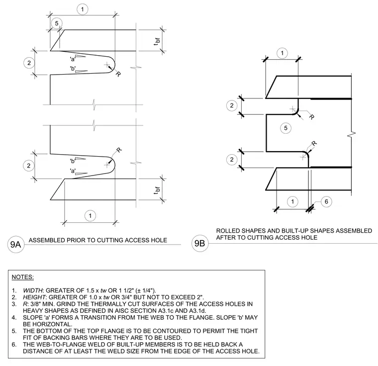
Standard access hole geometry for rolled shapes and built-up members features configurations for assemblies cut either prior to or after fabrication. The access hole width is specified as the greater of 1.5 times the web thickness or one and one-half inches, while the height is the greater of 1.0 times the web thickness or three-quarters of an inch but not to exceed two inches. A minimum radius of three-eighths of an inch is required, with thermally cut surfaces ground in accordance with AISC standards. Slope 'a' provides a transition from the web to the flange, and slope 'b' may remain horizontal. The bottom of the top flange is contoured to allow a tight fit for backing bars, and the web-to-flange weld on built-up members is held back by at least the weld size from the access hole edge.
NOTES: 1. WIDTH : GREATER OF 1.5 x tw OR 1 1/2" (± 1/4"). 2. HEIGHT : GREATER OF 1.0 x tw OR 3/4" BUT NOT TO EXCEED 2". 3. R : 3/8" MIN. GRIND THE THERMALLY CUT SURFACES OF THE ACCESS HOLES IN HEAVY SHAPES AS DEFINED IN AISC SECTION A3.1c AND A3.1d. 4. SLOPE 'a' FORMS A TRANSITION FROM THE WEB TO THE FLANGE. SLOPE 'b' MAY BE HORIZONTAL. 5. THE BOTTOM OF THE TOP FLANGE IS TO BE CONTOURED TO PERMIT THE TIGHT FIT OF BACKING BARS WHERE THEY ARE TO BE USED. 6. THE WEB-TO-FLANGE WELD OF BUILT-UP MEMBERS IS TO BE HELD BACK A DISTANCE OF AT LEAST THE WELD SIZE FROM THE EDGE OF THE ACCESS HOLE. 9B 1 6 5 8 3/4" 4 5/16" 1 ROLLED SHAPES AND BUILT-UP SHAPES ASSEMBLED AFTER TO CUTTING ACCESS HOLE 2 R 2 R bf 2 R 1 t bf R t 5 1 2 'a' 'b' 'a' 'b' 9A ASSEMBLED PRIOR TO CUTTING ACCESS HOLE
Members view this detail in full resolution, download the CAD files (SVG, PDF), and can adapt it in the built-in CAD editor — export DXF, DWG, or PDF.
Start membership