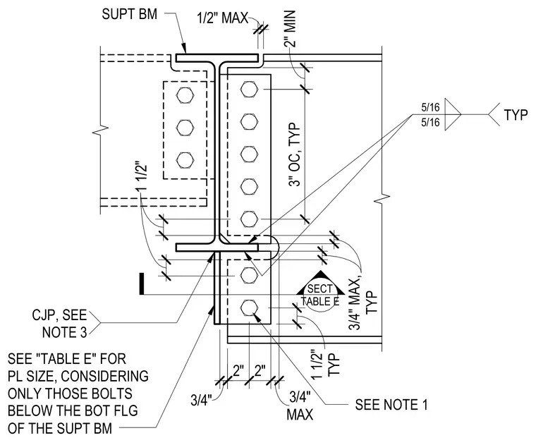
A beam frames into a supporting beam using bolted web connections and welded elements. The supported beam web is connected via vertical angles or plates fastened with multiple rows of bolts spaced at three inches on center typical. Weld symbols indicate five-sixteenth-inch fillet welds joining the connection plates. Plate sizes are determined per Table E, considering only those bolts located below the bottom flange of the supporting beam. Clearances include a half-inch maximum gap at the top flange and specific edge distances for the bolt layout.
SECT TABLE E SUPT BM CJP, SEE NOTE 3 3/4" 2" 2" MAX 3/4" TYP 5/16 5/16 3/4" 1 1/2" 3/4" 1 1/2" 12" 1/2" MAX TYP 1 1/2" SEE NOTE 1 SEE "TABLE E" FOR PL SIZE, CONSIDERING ONLY THOSE BOLTS BELOW THE BOT FLG OF THE SUPT BM 2" MIN 3" OC, TYP 3/4" MAX, TYP
Members view this detail in full resolution, download the CAD files (SVG, PDF), and can adapt it in the built-in CAD editor — export DXF, DWG, or PDF.
Start membership