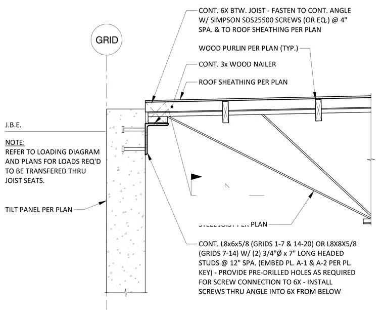
This assembly features a steel joist supported by a continuous embedded angle anchored into a concrete tilt-up panel. The angle is specified as either L8x6x5/8 or L8x8x5/8, secured with two 3/4-inch diameter by 7-inch long headed studs spaced at 12 inches on center. A continuous 3-inch wood nailer sits atop the angle, supporting the roof sheathing and wood purlins. The wood purlins are fastened to the continuous angle from below using Simpson SDS25500 screws or equivalent, spaced at 4 inches on center. The assembly requires pre-drilled holes in the angle to facilitate the screw connection to the wood members.
F GRID TILT PANEL PER PLAN ROOF SHEATHING PER PLAN J.B.E. NOTE: REFER TO LOADING DIAGRAM AND PLANS FOR LOADS REQ'D TO BE TRANSFERED THRU JOIST SEATS. 1/4 3 CONT. 3x WOOD NAILER STEEL JOIST PER PLAN CONT. L8x6x5/8 (GRIDS 1-7 & 14-20) OR L8X8X5/8 (GRIDS 7-14) W/ (2) 3/4"Ø x 7" LONG HEADED STUDS @ 12" SPA. (EMBED PL. A-1 & A-2 PER PL. KEY) - PROVIDE PRE-DRILLED HOLES AS REQUIRED FOR SCREW CONNECTION TO 6X - INSTALL SCREWS THRU ANGLE INTO 6X FROM BELOW WOOD PURLIN PER PLAN (TYP.) CONT. 6X BTW. JOIST - FASTEN TO CONT. ANGLE W/ SIMPSON SDS25500 SCREWS (OR EQ.) @ 4" SPA. & TO ROOF SHEATHING PER PLAN SECTION S4.2 3/4" = 1'-0" 05
Members view this detail in full resolution, download the CAD files (SVG, PDF), and can adapt it in the built-in CAD editor — export DXF, DWG, or PDF.
Start membership