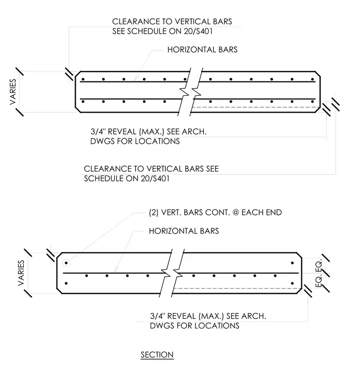
Two concrete arch sections detail the placement and clearance requirements for horizontal and vertical reinforcing bars. Two continuous vertical bars are positioned at each end, supplemented by horizontal bars running along the member length. A maximum three-quarter-inch reveal is specified, with exact locations coordinated through the architectural drawings. Vertical bar clearance distances are referenced to the schedule on sheet 20/S401.
CLEARANCE TO VERTICAL BARS SEE SCHEDULE ON 20/S401 3/4" REVEAL (MAX.) SEE ARCH. DWGS FOR LOCATIONS CLEARANCE TO VERTICAL BARS SEE SCHEDULE ON 20/S401 VARIES HORIZONTAL BARS 3/4" REVEAL (MAX.) SEE ARCH. DWGS FOR LOCATIONS SECTION VARIES HORIZONTAL BARS (2) VERT. BARS CONT. @ EACH END EQ. EQ.
Members view this detail in full resolution, download the CAD files (SVG, PDF), and can adapt it in the built-in CAD editor — export DXF, DWG, or PDF.
Start membership