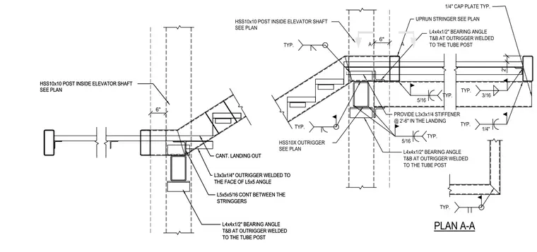
An HSS10x10 structural steel tube post located inside an elevator shaft supports stair landing outriggers sized per plan. A continuous L5x5x5/16 angle spans between the stringgers with L3x3x1/4 outriggers welded to its face. Top and bottom bearing angles formed from L4x4x1/2 are welded to the tube post at the outrigger locations. A three-sixteenths inch fillet weld and quarter-inch cap plates are utilized throughout typical joints. Additional L3x3x1/4 stiffeners are spaced at two feet six inches within the landing uprun stringer.
6" 6" 2" A A TYP. TYP. TYP. 3/16 TYP. 1/4" TYP. 5/16 TYP. 5/16 TYP. CANT. LANDING OUT L3x3x1/4" OUTRIGGER WELDED TO THE FACE OF L5x5 ANGLE L5x5x5/16 CONT BETWEEN THE STRINGGERS HSS10x10 POST INSIDE ELEVATOR SHAFT SEE PLAN L4x4x1/2" BEARING ANGLE T&B AT OUTRIGGER WELDED TO THE TUBE POST CANT. LANDING OUT L3x3x1/4" OUTRIGGER WELDED TO THE FACE OF L5x5 ANGLE L5x5x5/16 CONT BETWEEN THE STRINGGERS HSS10x10 POST INSIDE ELEVATOR SHAFT SEE PLAN L4x4x1/2" BEARING ANGLE T&B AT OUTRIGGER WELDED TO THE TUBE POST HSS10x10 POST INSIDE ELEVATOR SHAFT SEE PLAN HSS10X OUTRIGGER SEE PLAN PROVIDE L3x3x1/4 STIFFENER @ 2'-6" IN THE LANDING UPRUN STRINGER SEE PLAN L4x4x1/2" BEARING ANGLE T&B AT OUTRIGGER WELDED TO THE TUBE POST L4x4x1/2" BEARING ANGLE T&B AT OUTRIGGER WELDED TO THE TUBE POST PLAN A-A 1/4" CAP PLATE TYP.
Members view this detail in full resolution, download the CAD files (SVG, PDF), and can adapt it in the built-in CAD editor — export DXF, DWG, or PDF.
Start membership