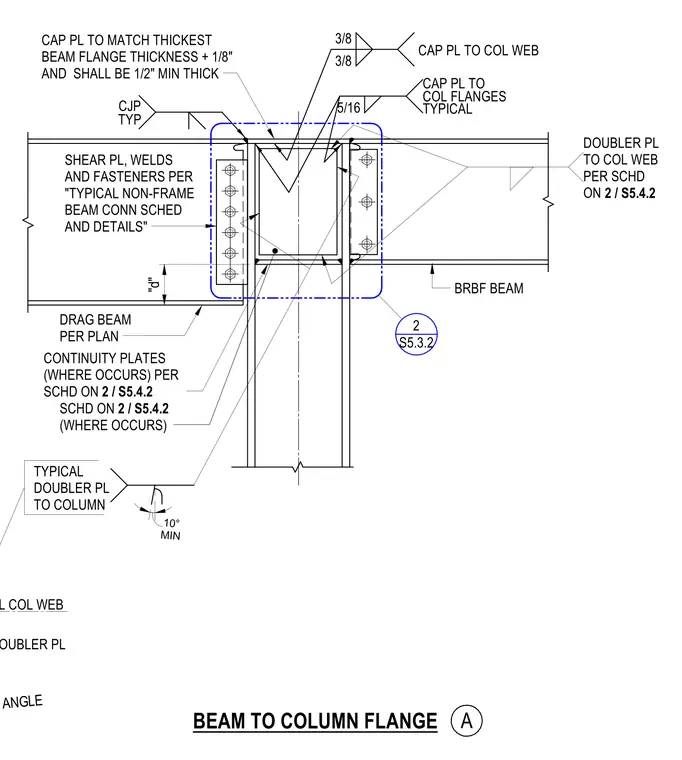
A buckling-restrained braced frame beam frames into a structural steel column with a cap plate matching the thickest beam flange thickness plus one-eighth inch, with a one-half inch minimum thickness. A shear plate connects the beam web with welds and fasteners sized per the typical non-frame beam connection schedule and details. Complete joint penetration welds are specified typically, with three-eighths inch welds at the cap plate to column web and five-sixteenths inch welds at the column flanges. Continuity plates and column web doubler plates are installed where required per schedule on sheet S5.4.2.
BRBF BEAM CAP PL TO MATCH THICKEST BEAM FLANGE THICKNESS + 1/8" AND SHALL BE 1/2" MIN THICK SHEAR PL, WELDS AND FASTENERS PER "TYPICAL NON-FRAME BEAM CONN SCHED AND DETAILS" DRAG BEAM PER PLAN CONTINUITY PLATES (WHERE OCCURS) PER SCHD ON 2 / S5.4.2 CJP TYP 3/8 3/8 CAP PL TO COL WEB 5/16 CAP PL TO COL FLANGES TYPICAL BEAM TO COLUMN FLANGE A "d" TYPICAL DOUBLER PL TO COLUMN CL COL WEB DOUBLER PL MIN GROOVE ANGLE MIN 10° DOUBLER PL TO COL WEB PER SCHD ON SCHD ON 2 / S5.4.2 (WHERE OCCURS) 2 / S5.4.2 S5.3.2 2
Members view this detail in full resolution, download the CAD files (SVG, PDF), and can adapt it in the built-in CAD editor — export DXF, DWG, or PDF.
Start membership