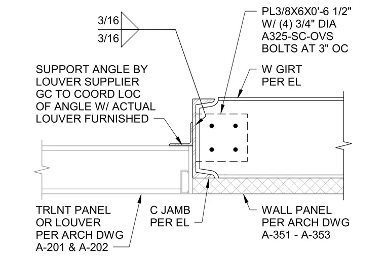
A three-eighths-inch thick by six-inch wide by six-and-a-half-inch long steel plate connects to a wide-flange girt using four three-quarter-inch diameter ASTM A325 slip-critical oversized bolts spaced at three inches on center. A support angle provided by the louver supplier fastens adjacent to the translucent panel or louver assembly, requiring the general contractor to coordinate its location with the actual louver furnished. The exterior wall panel and channel jamb are installed per architectural drawings. Fillet welds of three-sixteenths inch secure the steel components as indicated.
PL3/8X6X0'-6 1/2" W/ (4) 3/4" DIA A325-SC-OVS BOLTS AT 3" OC 3/16 3/16 TRLNT PANEL OR LOUVER PER ARCH DWG A-201 & A-202 SUPPORT ANGLE BY LOUVER SUPPLIER GC TO COORD LOC OF ANGLE W/ ACTUAL LOUVER FURNISHED W GIRT PER EL C JAMB PER EL WALL PANEL PER ARCH DWG A-351 - A-353
Members view this detail in full resolution, download the CAD files (SVG, PDF), and can adapt it in the built-in CAD editor — export DXF, DWG, or PDF.
Start membership