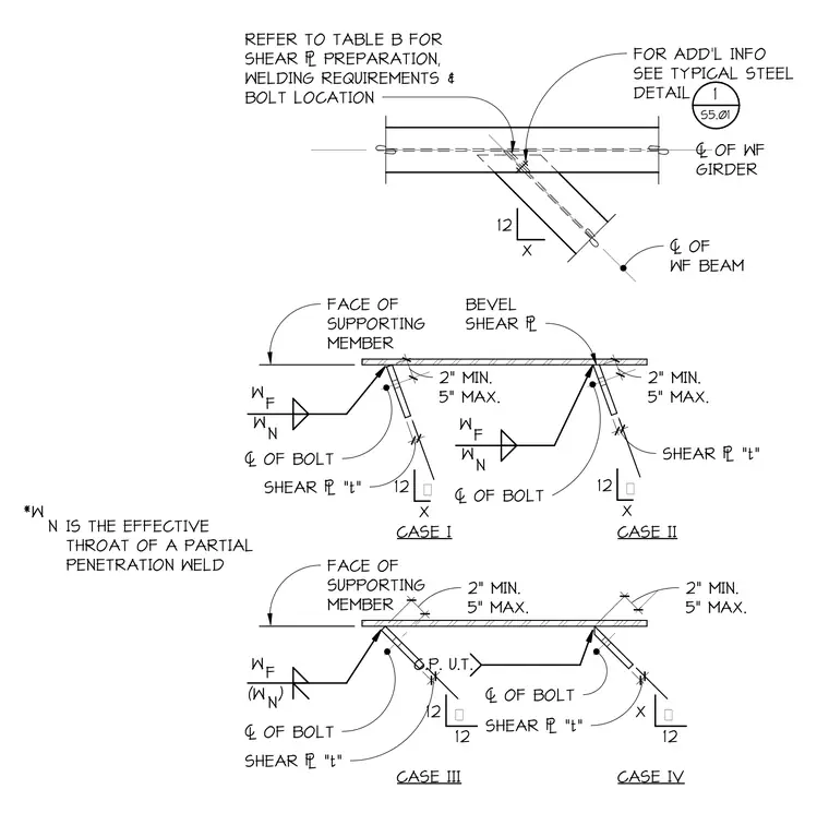
Four case variations connect a wide flange beam to a wide flange girder using a bevel shear plate. The connection utilizes partial penetration welds with an effective throat dimension, alongside specified bolt locations. Minimum and maximum edge and spacing distances govern the placement of the shear plate relative to the face of the supporting member. Each case outlines distinct weld preparation configurations and bolt centerlines for structural steel framing integration.
*W N IS THE EFFECTIVE THROAT OF A PARTIAL PENETRATION WELD FOR ADD'L INFO SEE TYPICAL STEEL DETAIL 7 OF WF GIRDER 12 X 7 OF WF BEAM REFER TO TABLE B FOR SHEAR PREPARATION, WELDING REQUIREMENTS & BOLT LOCATION W F W N FACE OF SUPPORTING MEMBER BEVEL SHEAR 2 1 / 2" 2" MIN. 5" MAX. 3/4 " SHEAR "t" Θ W F W N 2" 2" MIN. 5" MAX. 3/4 " 12 X SHEAR "t" Θ FACE OF SUPPORTING MEMBER CASE I CASE II W F (W ) N 7 OF BOLT 7 OF BOLT 7 OF BOLT 2 1/ 2" 2" MIN. 5" MAX. 3/4 " SHEAR "t" 12 12 Θ C.P. U.T. 2 1/ 2" 2" MIN. 5" MAX. 7 OF BOLT 3/4 " SHEAR "t" X 12 Θ CASE III CASE IV 12 X 1 S5.01
Members view this detail in full resolution, download the CAD files (SVG, PDF), and can adapt it in the built-in CAD editor — export DXF, DWG, or PDF.
Start membership